Tanning bed support structure and a tanning bed comprising the same

a technology of support structure and tanning bed, which is applied in the field of portable tanning equipment, can solve the problems of increasing the risk of skin cancer of various types, affecting the health of the person running the tanning facility, and affecting the quality of the tanning bed, so as to achieve quick and easy disassembly and transportation. , the effect of quick change of position

Inactive Publication Date: 2005-11-03
DIXON CHARLES M
View PDF24 Cites 4 Cited by
  • Summary
  • Abstract
  • Description
  • Claims
  • Application Information

AI Technical Summary

Benefits of technology

[0014] Preferably, the axle rotates reversibly from a first position to a second position, where the tanning bed is in a horizontal position when the axle is in said first position, and the tanning bed is in a vertical position when the axle is in said second position. This allows customers to tan in a standing position when the tanning bed is in its vertical position, or to tan in a prone position when the tanning bed is in its horizontal position. The motorized rotation of the axle allows the tanning salon proprietor to quickly change the position of the tanning bed depending on his customer's expressed preference. If desired, the tanning bed may also be rotated manually.
[0015] In another embodiment, the tanning bed is removably mounted to the axle. This allows the apparatus to be quickly and easily disassembled for transportation, or to replace a worn out or obsolete tanning bed with a new tanning bed while retaining the support framework.

Problems solved by technology

However, there are certain risks associated with this, as the sun emits a wide range of ultraviolet frequencies, many of which are deleterious to human health.
Of even greater concern is the fact that sunburns during the tanning process greatly increases the risk of skin cancers of various types.
This leads to a problem for the person running the tanning facility.
Further, he has to pay rent on increased space for storage and maintenance of the two sets of equipment.
Additionally, tanning beds wear out over time and must be replaced.

Method used


Image

  • Tanning bed support structure and a tanning bed comprising the same
  • Tanning bed support structure and a tanning bed comprising the same
  • Tanning bed support structure and a tanning bed comprising the same

Examples


Embodiment Construction

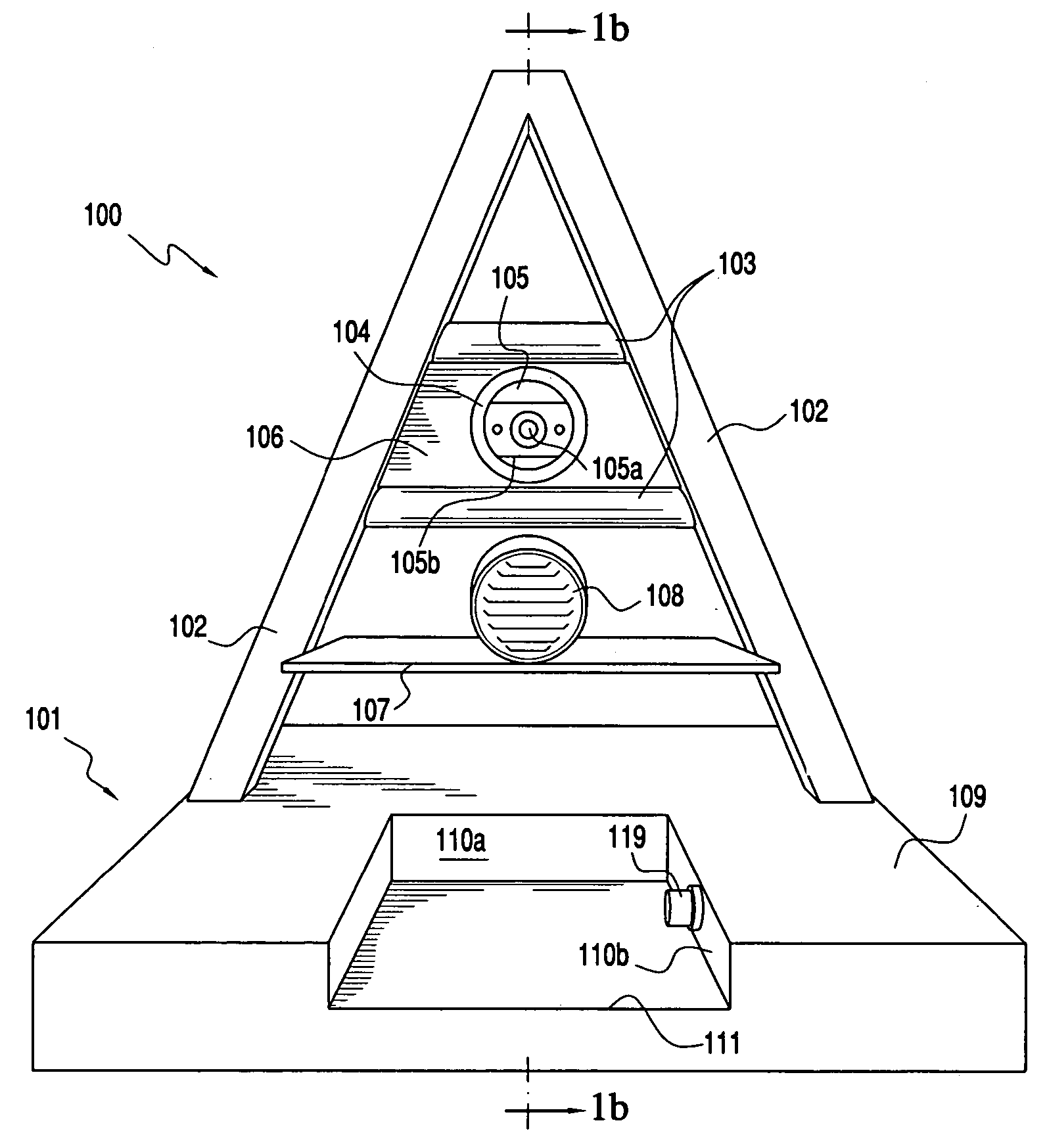
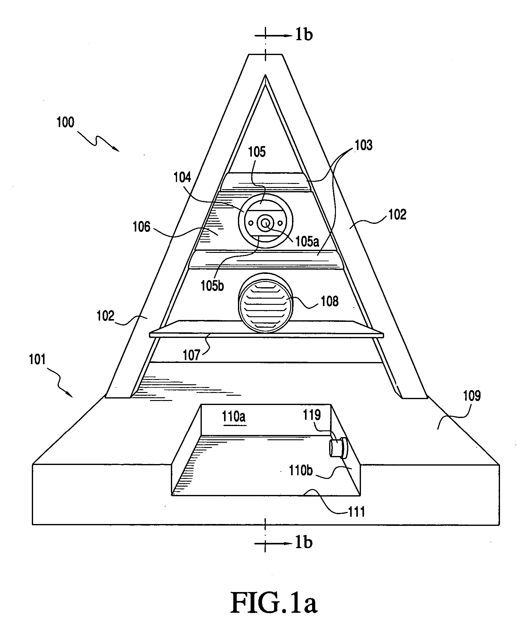
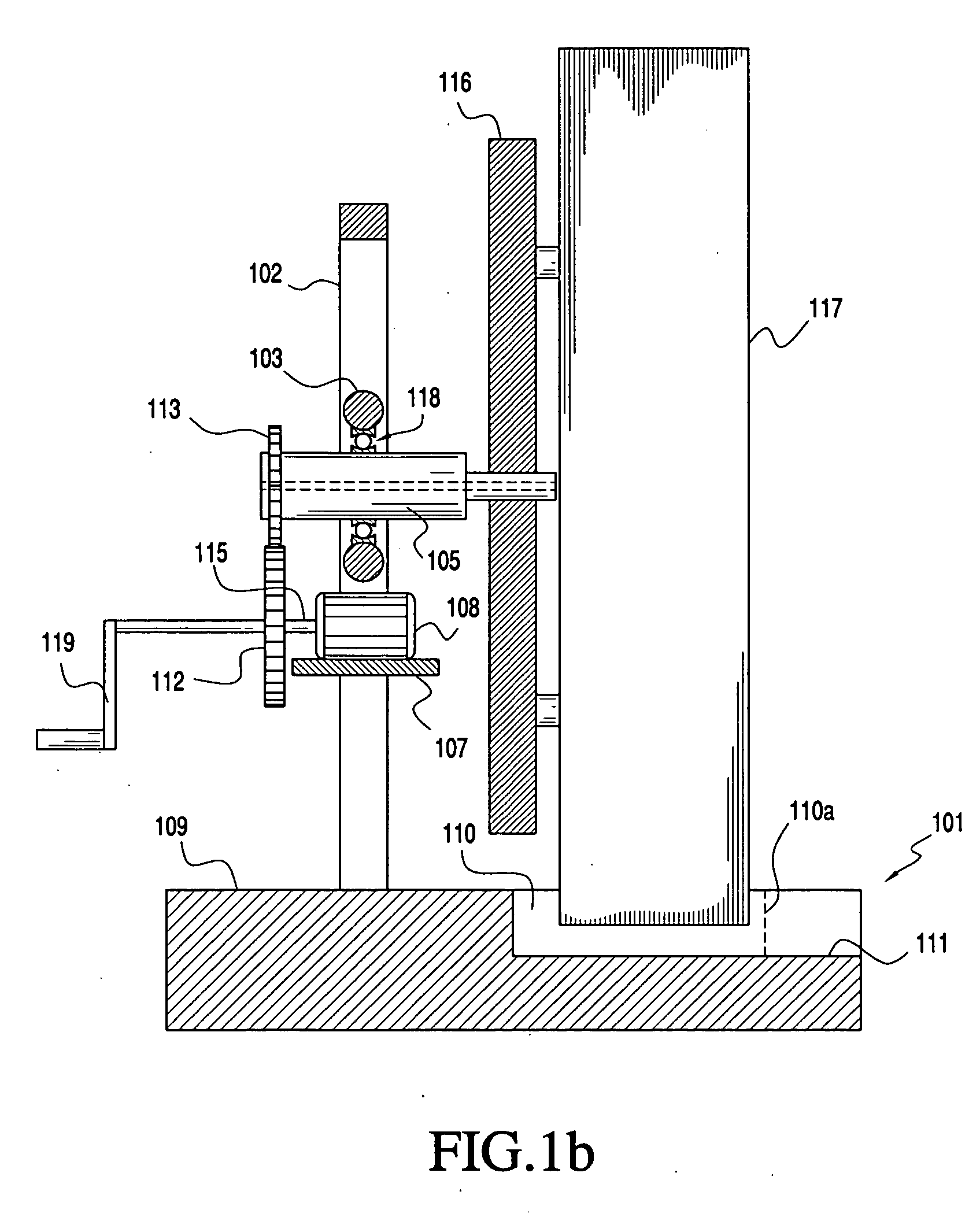
[0021] Referring now to the drawings, in which like numerals refer to like components or steps, there are disclosed broad aspects of the preferred embodiments of the present invention. FIGS. 1a and 1b show a framework 100 for supporting a tanning bed, mounted on a base 101. The base 101 includes two slanted support members 102, preferably made from a metal tube or rod. Support members 102 may be made from iron, steel, aluminum, or titanium. Alternatively, members 102 may be made from a high-strength composite polymeric material, such as a fiber-reinforced plastic. For reasons of both weight and cost, however, the preferred material for members 102 is a tubular steel material. Two crossbeams 103 run between members 102, and provide reinforcement for the members 102. An axle-supporting tubular element 104 is mounted between crossbeams 103, and a rotatable axle 105 passes longitudinally through element 104. There is a longitudinal bore 105a through axle 105. The axle is preferably cyli...


PUM


Abstract

A framework for supporting a rotatably mounted tanning bed, comprising a support frame; an axle rotatably mounted to said support frame, said axle being adapted to non-rotatably support a tanning bed; and a motor adapted to reversibly rotate the axle from a first position to a second position, wherein said tanning bed is in a horizontal position when the axle is in said first position, and said tanning bed is in a vertical position when the axle is in said second position; and a tanning machine comprising a tanning bed mounted on said framework.

Description

BACKGROUND OF THE INVENTION [0001] 1. Field of the Invention [0002] This invention relates generally to a tanning apparatus, and more particularly to a portable tanning apparatus capable of tanning the entire body of a person. More particularly, the invention relates to a portable apparatus for allowing a person to tan while in either a reclining position or a standing position. [0003] 2. Description of Related Art [0004] In our culture, suntanned skin is considered highly desirable and, as a result, each year people willingly expose themselves to the sun for extended periods to obtain a golden or bronze suntan. However, there are certain risks associated with this, as the sun emits a wide range of ultraviolet frequencies, many of which are deleterious to human health. Ultraviolet light having a wavelength of 315 to 380 nanometers (UVA light) is most beneficial for tanning, and is comparatively safe. Other types of ultraviolet light such as light having a wavelength between 280 and ...

Claims


Application Information

Patent Timeline
Patent Type & Authority Applications(United States)
IPC IPC(8): A61N5/00A61N5/06
CPCA61N2005/0633A61N5/0614
Inventor DIXON, CHARLES M.
Owner DIXON CHARLES M
Why Eureka
Try Eureka