Release tool for a drill string inside blowout preventer

Active Publication Date: 2015-03-12
DWJ
View PDF2 Cites 5 Cited by
  • Summary
  • Abstract
  • Description
  • Claims
  • Application Information

AI Technical Summary

Benefits of technology

[0008]In accordance with the present disclosure, improved release tools for IBOPs and methods of assembling the release too

Problems solved by technology

One of the above patents, U.S. Pat. No. 4,403,628, implies in Col. 3 of the patent that assembling an IBOP into a drill stem and removing the IBOP therefrom as just described, including lifting and manipulating the IBOP, is conveniently performed, but this is contrary to experience, as accidents can and have occurred.
While the “iron” (slang term for rig tools) is used to being dropped and banged around the rig, the rig workers have the difficult tasks of not only using the rig hoist to pick up the IBOP/release tool, u

Method used


Image

  • Release tool for a drill string inside blowout preventer
  • Release tool for a drill string inside blowout preventer
  • Release tool for a drill string inside blowout preventer

Examples


embodiment 100

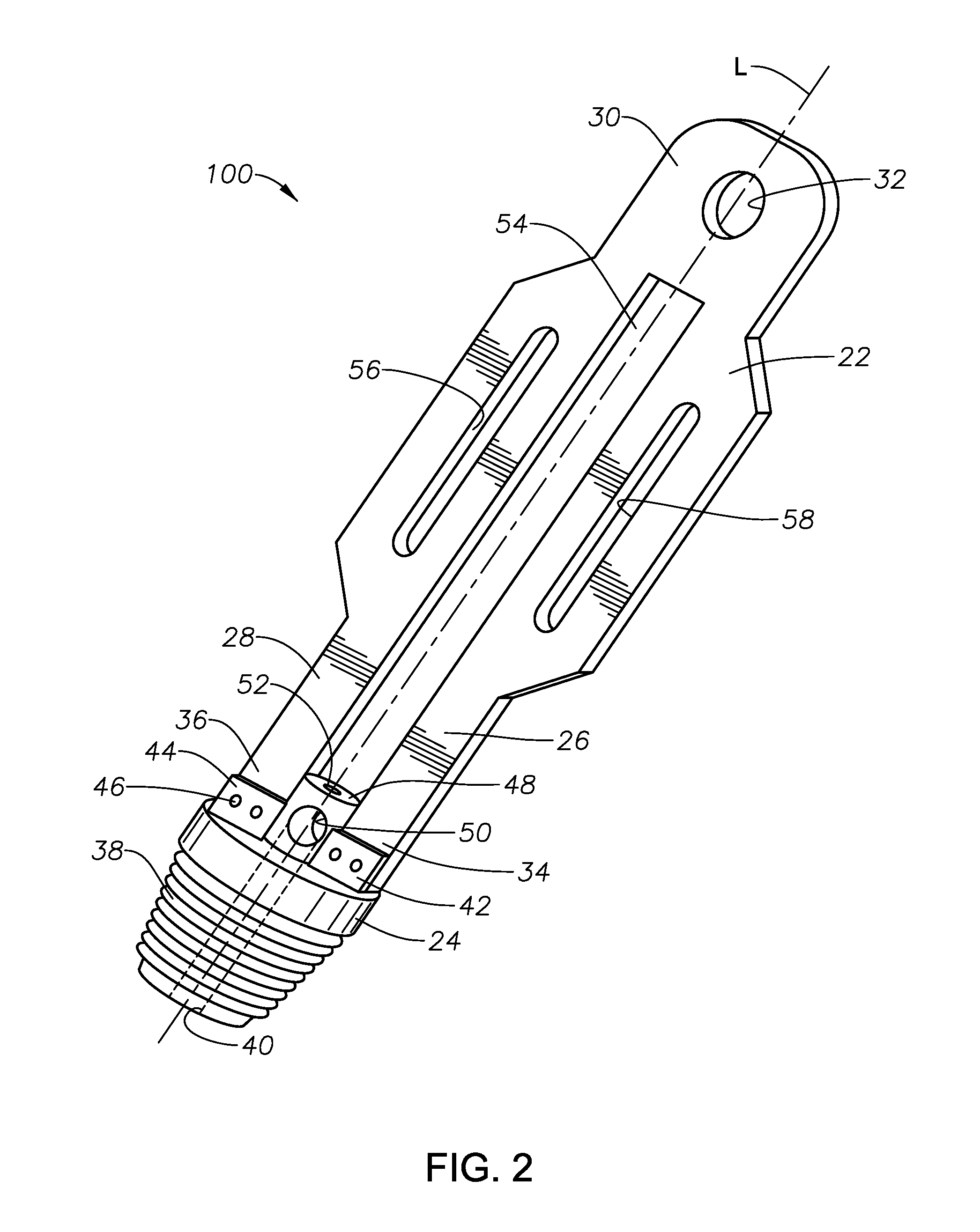
[0049]With these problems in mind, the release tools of the present disclosure were developed. FIG. 2 is a schematic perspective view of one release tool body embodiment 100 within the present disclosure. Release tool body 100 includes an upper “flat iron” section 22 having a longitudinal axis “L”, and a lower tubular section 24 of same longitudinal axis. Upper section 22 is comprised of two longitudinal members 26, 28, joined by a top manipulating end 30. Upper section 22 is a one-piece, formed, planar, metallic component with no welds, brazing or components welded or brazed thereto. This eliminates the need for pull testing (tensile testing) in offshore applications. Longitudinal members 26, 28 define a central open region 54 there between, each longitudinal member having a lower end 34, 36, respectively. Top manipulating end 30 includes one or more lifting features 32 formed therein configured to accept one or more manipulator cables or chains (not illustrated), the one or more f...

embodiment 80

[0058]In certain embodiments, an optional rod cap 80 may be placed on the top of release rod 16 to make it easier to push down. FIGS. 6A, 6B, and 6C are schematic perspective, end, and side elevation (partially in phantom) views, respectively, of an optional rod cap 80 useful in certain embodiments. In embodiment 80, rod cap 80 includes a flange or lateral extension 81 having a knurled rim 82, and a hollow shaft 83 having a non-threaded inner surface 84. Dimensions D, E, F, G, and H may vary, and will largely be dictated by diameter of release rod 16. Dimension D may range from about 30 to about 90 mm, or from about 50 to about 70 mm; dimension E may range from about 10 to about 30 mm, or from about 10 to about 20 mm; dimension F may range from about 15 to about 30 mm, or from about 20 to about 30 mm; dimension G may range from about 5 to about 25 mm, or from about 10 to about 20 mm; and dimension H may range from about 20 to about 60 mm, or from about 30 to about 50 mm. Rod caps wi...

embodiment 400

[0062]Still referring to FIG. 8 and embodiment 400, the various dimensions and their ranges may be as listed in Table 1, acknowledging that dimensions outside of these ranges may be acceptable:

TABLE 1Dimensions of Embodiment 400DimensionEmbodiment 400 (inch)Preferred Range (inch)A'10.5515-25B'2.7241-10C'1.5000.5-5  D'3.0001-10E'15.00010-30 F'7.5005-15G'1.8991-5 H2.1001-5 I5.5002-10J1.6851-3 K0.7760.5-2  M5.0552-10N0.2500.125-2   O3.0281-5 P1.0000.25-3   Q0.6250.25-3   R2.891-5 S4.7162-10T6.5003-15U2.5001-10V2.0001-5 W5.0003-20X14.507-40Y1.5000.5-5  Z0.5000.3-3  61a0.2500.125-2   

[0063]FIGS. 9 and 10 illustrate schematic perspective and side elevation views, respectively, of embodiment 500 of upper section 22 of embodiment 400 having two hand guards 502, 504 attached thereto using bolts 506, 508. In embodiment 500, there would be six bolts 506, and six bolts 508, corresponding to the twelve through holes 61 illustrated in FIG. 8. It will be understood that a similar arrangement would...


PUM


Abstract

Inside blowout preventer release tool body having a one-piece planar upper section and a one-piece tubular lower section. In one embodiment, the upper section includes a pair of longitudinal members defining a central open region, the longitudinal members joined at one end having a formed lifting feature configured to accept a manipulator cable or chain. The lifting feature is positioned such that when the release tool body and an inside blowout preventer connected thereto are lifted by the rig hoist using cables, chains, and the like, they are easily moved over, aligned with, and connected with a working drillpipe while minimizing possibility of slipping off the cables or chains. The lower section includes a threaded end mating with a mating end of an inside blowout preventer, a central longitudinal bore to accept a release rod, and an upper end formed to accept the lower ends of the longitudinal members of the upper section. In one embodiment, elongate slots in each longitudinal member define one or more manipulating handles for a rig worker, machine, or tool. In other embodiments a pair of generally horizontal hand holds are defined in each longitudinal member.

Description

BACKGROUND INFORMATION[0001]1. Technical Field[0002]The present disclosure relates to apparatus and methods in the onshore and marine (offshore) hydrocarbon exploration, production, drilling, well completion, well intervention, and leak containment fields. More particularly, the present disclosure relates to release tools for inside blowout preventers.[0003]2. Background Art[0004]A “blowout (or blow out) preventer”, commonly known as a“BOP”, is a valve that may be used to prevent a well, usually a hydrocarbon producing well, from flowing uncontrollably. An “inside BOP” (also sometimes referred to as an “internal BOP”, “IBOP”, “kelly valve”, or “kelly cock”) is a BOP inside a drillpipe or drillstring, usually used to prevent the well from flowing uncontrollably up the drillstring. Industry standards require having an IBOP for every string of pipe in the hole on every rig that is working.[0005]Currently, IBOPs, which may weight 300 pounds or more, have no lifting eyes on their cap (al...

Claims


Application Information

Patent Timeline
IPC IPC(8): E21B34/14
CPCE21B34/14E21B34/08E21B19/00E21B21/10
Inventor WILLIAMS, DONALD L.
Owner DWJ
Why Eureka
Try Eureka