Turbomolecular pump

a technology of rotor blades and pumps, applied in the direction of machines/engines, stators, liquid fuel engines, etc., can solve the problems of 63 of the rotor blades being damaged

Inactive Publication Date: 2002-01-01
EDWARDS JAPAN
View PDF16 Cites 24 Cited by
  • Summary
  • Abstract
  • Description
  • Claims
  • Application Information

AI Technical Summary

Problems solved by technology

For that reason, in the case where a large fluctuation occurred in a load of gas due to malfunction, etc. of valves attached to a vacuum chamber, the stator blades wer...

Method used


Image

  • Turbomolecular pump
  • Turbomolecular pump
  • Turbomolecular pump

Examples


first embodiment

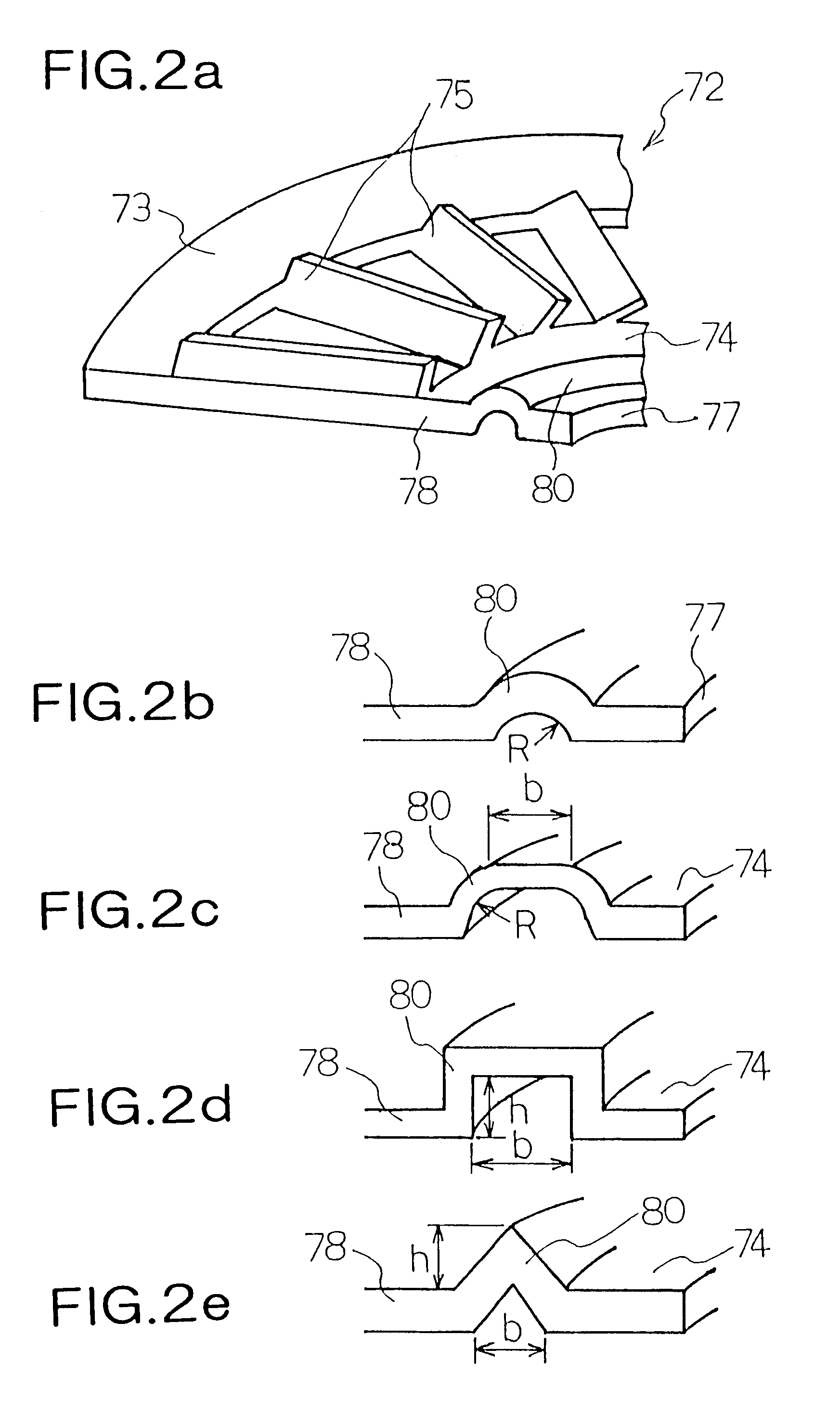
FIGS. 2(a) to 2(e) show the structure of the stator blade 72 according to the present invention.

As shown in FIG. 2(a), the stator blade 72 is constructed of an outer ring portion 73 part of the outer circumference side of which is sandwiched in the circumferential direction by the spacers 71, the inner ring portion 74, and a plurality of blades 75 both ends of which are radially supported with a predetermined angle by the outer ring portion 73 and the inner ring portion 74. The inner diameter of the inner ring portion 74 is formed larger than the outer diameter of the rotor body 61, so that the inner circumferential plane 77 of the inner ring portion 74, and the outer circumferential plane 65 of the rotor body 61 do not contact with each other (refer to FIG. 11(a)).

A rib structure portion 80 that functions as the reinforcement member is formed at the inner ring portion 74. This rib structure portion 80 is formed in the circumferential direction from an end face 78 of the two-divided...

second embodiment

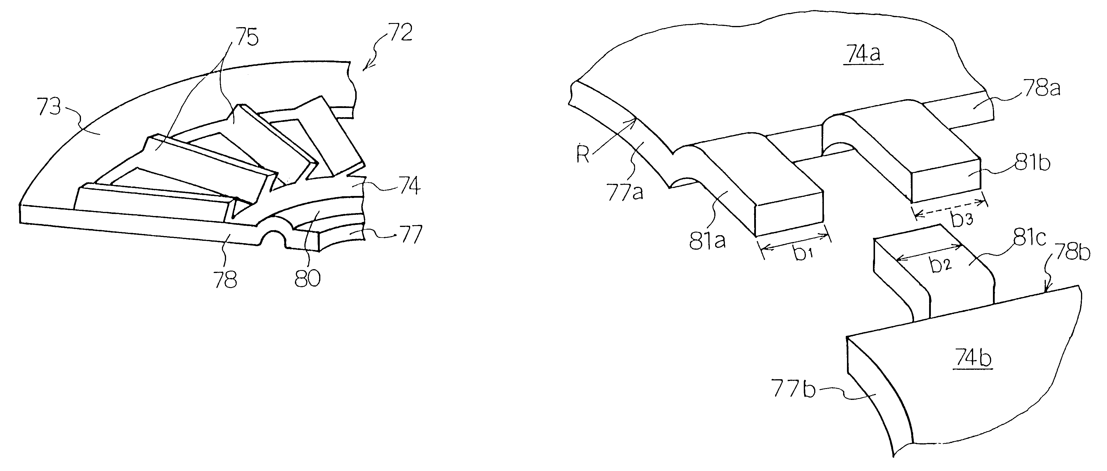
FIGS. 3(a) and 3(b) shows the structure of the stator blade 72 according to the present invention, in which both end portions of inner ring portions facing to each other are shown.

In FIGS. 3(a) and 3(b), one end out of a pair of two-divided inner ring portions 74 is denoted by reference symbol 74a, and the other end is denoted by reference symbol 74b. Further, if a right side end portion of the both inner ring portions 74a and 74b viewed from the rotor axis 18 side is assumed as one end portion, and a left side end portion is assumed as the other end portion, the shapes of the one end portion and the other end portion of the inner ring portion 74a are formed identical to that of the inner ring portion 74b. FIG. 3(a) shows the one end portion of the inner ring portion 74a and the other end portion of the inner ring portion 74b.

Note that the relationship between the one end portion and the other end portion of the inner ring portions 74a and 74b is the same as in modification examples...

third embodiment

FIG. 6 is a conceptual view showing arrangements of a stator blade 72 according to the present invention.

In the third embodiment, two-divided stator blades 72a and 72b and two-divided stator blades 72c and 72d are overlapped to constituted the stator blades 72 at the respective stages.

As shown in FIG. 6(a), the phase of the two-divided position of a pair of the stator blades 72a and 72b and that of the other pair of the stator blades 72c and 72d are shifted by 90.degree. to each other to be then overlapped. It should be noted that if the phases of the divided positions of the respective pairs do not coincide with each other, the shift thereof is not limited to 90.degree., for example, arbitrary angle such as 30.degree., 45.degree., or 60.degree. may be shifted.

FIGS. 6(b) to 6(d) show examples of the overlapping methods of the two pairs of the stator blades 72 according to the third embodiment of the present invention.

As a first method, as shown in FIG. 6(b), there is employed a case...


PUM


Abstract

A turbomolecular pump comprises a casing, a rotor having a rotor blades arranged in multiple stages in the casing axially thereof, and a stator having stator blades arranged in multiple stages and alternately located between the rotor blades. Each of the stator blades has an inner ring portion, an outer ring portion spaced-apart from the inner ring portion, and blades connected between the inner and outer ring portions along a circumferential direction thereof. Each of the blades has a first end connected to an outer peripheral edge of the inner ring portion and a second end opposite the first end connected to an inner peripheral edge of the outer ring portion. A reinforcement member is disposed on the inner ring portion of each of the stator blades along the entire circumference of the inner ring portion for reinforcing the stator blade.

Description

1. Field of the InventionThe present invention relates to a turbomolecular pump, and more particularly to a turbomolecular pump having improved stator blades.2. Description of the Related ArtA turbomolecular pump is widely used as a vacuum apparatus for a semiconductor manufacturing equipment.The turbomolecular pump has stator blades and rotor blades which are disposed on a stator portion and a rotor portion, respectively, in a multistage arrangement in an axial direction, and the rotor portion is rotated with a motor at high speed so that a vacuum (exhaust) action is performed.FIGS. 11(a) to 11(c) show the structures of the rotor blade and the stator blade of the turbomolecular pump described above. FIG. 11(a) shows an arrangement between the rotor blade and the stator blade, FIG. 11(b) is a sectional perspective view showing a rotor that is cut along upper and lower planes of the rotor blade, and FIG. 11(c) is a perspective view showing a part of the stator blade.As shown in FIG. ...

Claims


Application Information

Patent Timeline
IPC IPC(8): F04D19/04F04D19/00F04D29/40F04D29/54F04D29/38
CPCF04D29/542F04D19/042F04D29/38
Inventor KABASAWA, TAKASHI
Owner EDWARDS JAPAN
Why Eureka
Try Eureka