Multivision system, color calibration method and display

a multi-vision system and color calibration technology, applied in the field of multi-vision system, color calibration method and display, can solve the problems of uneven color display, inability to control the display color,

Inactive Publication Date: 2002-01-22
MITSUBISHI ELECTRIC CORP
View PDF33 Cites 153 Cited by
  • Summary
  • Abstract
  • Description
  • Claims
  • Application Information

AI Technical Summary

Problems solved by technology

Since only information obtained from the sensor R3 is the brightness information, such that a brightness setting responding to a surrounding environment only at that instance is optimally set, and a control of the display color was not possible.
Also, the sensor R3 of the conventional multi-visi

Method used


Image

  • Multivision system, color calibration method and display
  • Multivision system, color calibration method and display
  • Multivision system, color calibration method and display

Examples


embodiment 1

of the present invention is described below with reference to the drawings.

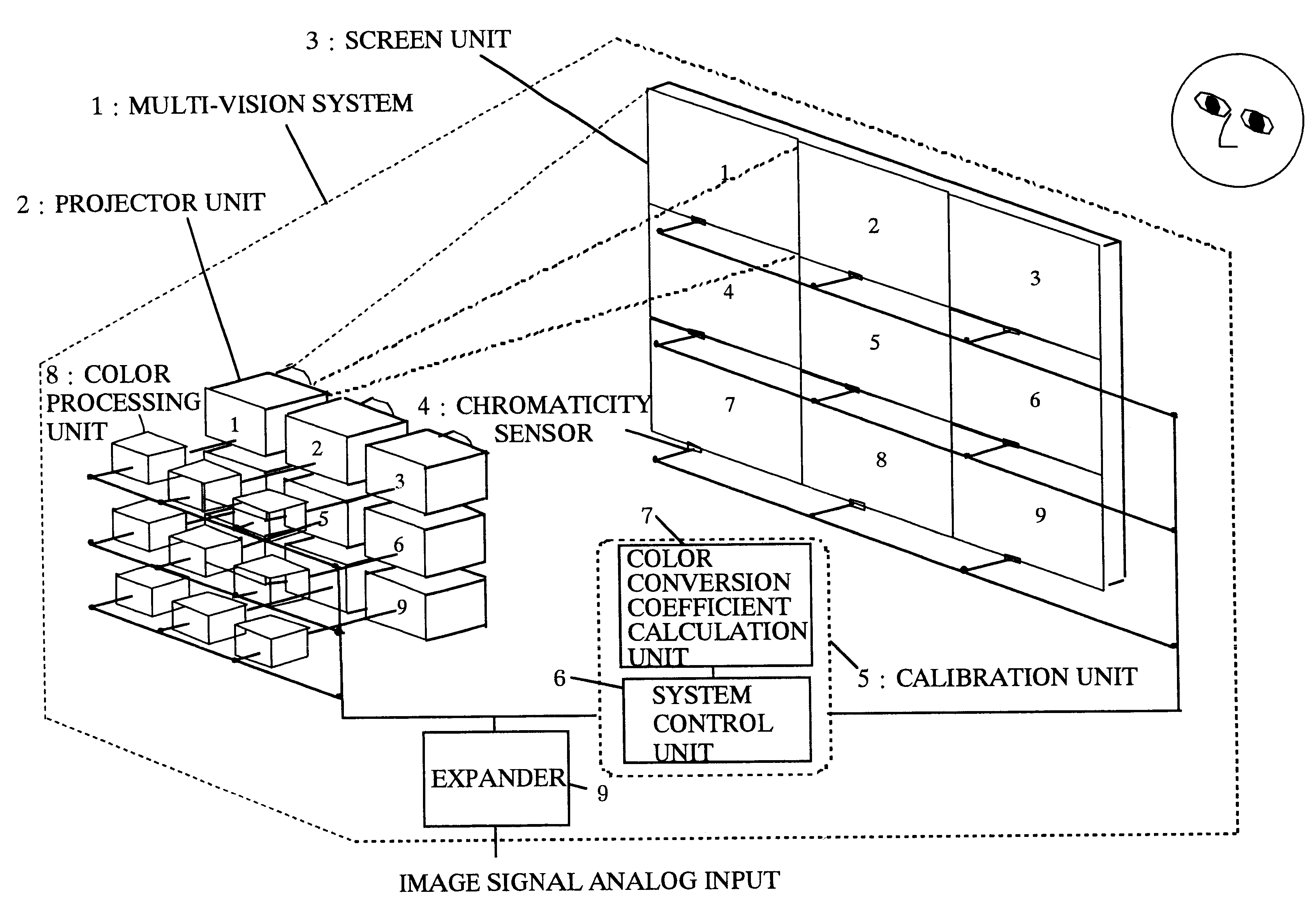
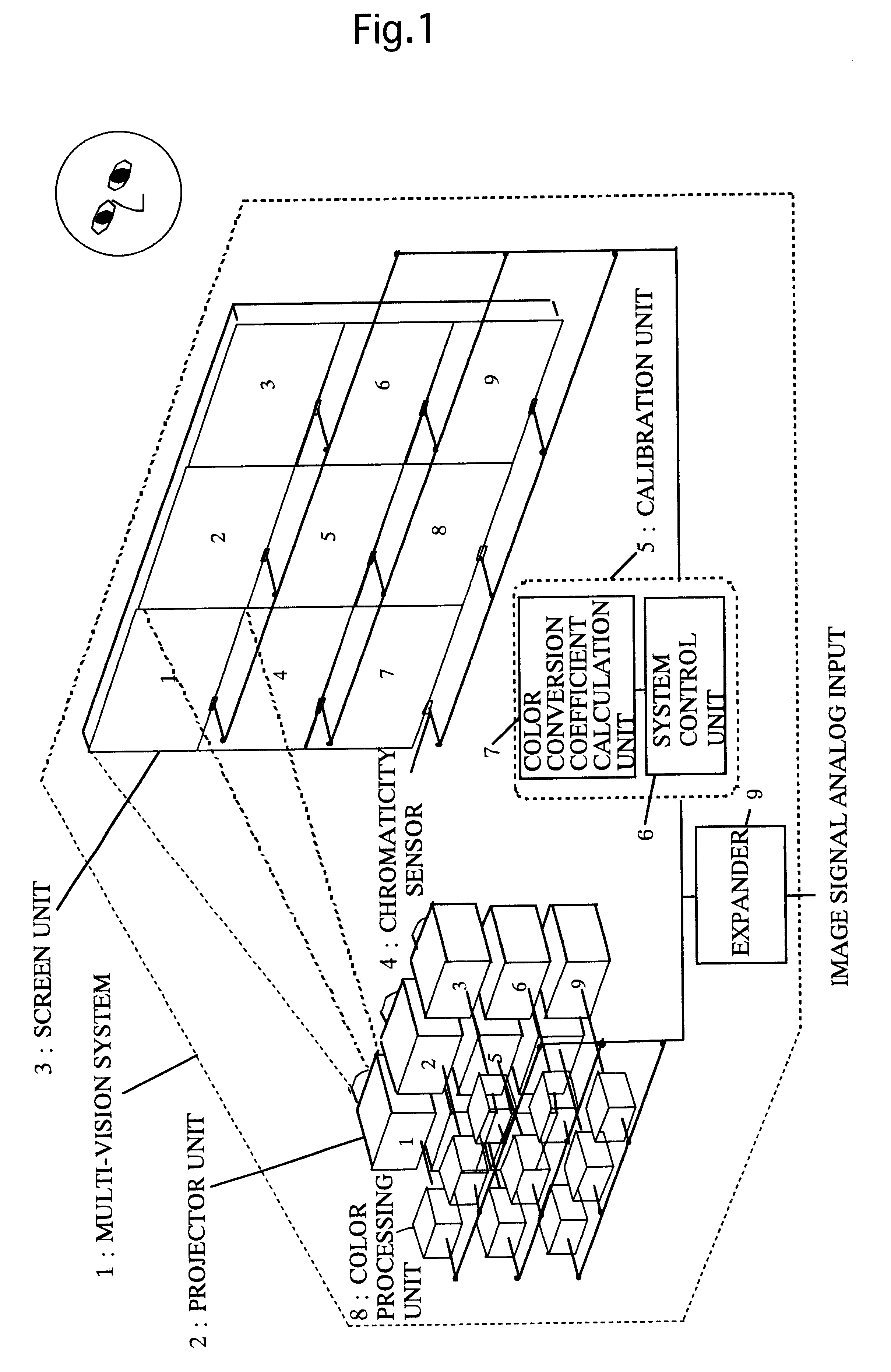
FIG. 1 shows the whole block chart of the multi-vision system comprising a color calibration function as one of the embodiments in the present invention.

With reference to FIG. 1, the numbered components will be described: an outline 1 of the multi-vision system; projector units 2; and screen units 3. Note that each one of the projector units 2 corresponds with one of the screen units 3. An analog image signal inputted to an expander 9 is enlarged and divided, and image signals are generated for every one of the projector units 2. The image signals are inputted to the projector units 2 via color processing units 8.

Also, chromaticity sensors 4 are set between the screen units 3. The chromaticity sensors 4 are positioned so as to be able to perform colorimetry of corresponding projector units 2 for the color of the light source without color conversion by the color processing unit 8. A calibration unit 5 is conf...

embodiment 2

Embodiment 2 of the present invention will be described with reference to the drawing.

FIG. 6 is the whole block chart of the multi-vision system provided with the color calibration function, showing one of the embodiments in the present invention.

The characteristic of embodiment 2 being different from embodiment 1 is that the positions of the chromaticity sensors 4 are outside of the multi-vision system, as illustrated in FIG. 6. Unlike embodiment 1, the sensor of the embodiment 2 does not perform colorimetry of the light source, but it performs colorimetry for the colors of the screen unit 3. Also, the sensor in embodiment 1 is measuring a light leaking to outside of the screen, however, in the system of embodiment 2, a color at the screen center is measured by the sensor. The method of calibration is same as embodiment 1.

According to the present embodiment, since the chromaticity sensors, which perform colorimetry of the plurality of the display units, are placed outside of the mu...

embodiment 3

Embodiment 3 of the present invention will be described with reference to the drawings.

FIG. 7 is the whole block chart of the multi-vision system provided with the color calibration function, showing one of the embodiments in the present invention.

The characteristic of embodiment 3 being different from embodiment 1 is that a smaller number of chromaticity sensors 4 than the number of display units are placed outside of the multi-vision system, as illustrated in FIG. 7. These chromaticity sensors 4 are arranged in a line on top a sensor unit 10. The number of chromaticity sensors 4 in the sensor unit 10 are same as the number of the display units that are aligned horizontally in one line. As illustrated in FIG. 7, the sensor unit 10 is provided with a mechanism that scans in parallel to multi-vision, which is a direction A (the mechanism not illustrated). While the sensor unit 10 scans the multi-vision in up and down directions, the sensor unit 10 performs colorimetry at a plurality ...


PUM


Abstract

A multi-vision system includes chromaticity sensors for performing colorimetry of a plurality of display units. From colorimetry results obtained from the chromaticity sensors, a color conversion coefficient calculation unit inside a color calibration unit calculates the color conversion coefficient that is characteristic of each display unit. Calculated color conversion coefficients are stored in a color processing unit. The color calibration for this multi-vision system displays representing colors without a color conversion, and from colorimetry results of the representing colors for all the display units, a target color is decided automatically. For all display units, the color conversion coefficients are automatically calculated so that the representing colors are able to be displayed as a target color.

Description

The present invention relates to color calibration of a display device and a multi-vision system comprising a plurality of display units.BACKGROUND ARTSFIGS. 16 and 17 from Japanese unexamined patent publication Hei7-72817 illustrate a part of the cross-sectional diagram and the block chart of an important part for the conventional multi-vision brightness control apparatus comprising the plurality of display units.Also, FIG. 18 is the flow chart showing an operation of the same multi-vision brightness control apparatus.Description to the numbered components indicated in FIGS. 16 and 17 follows: a screen R1; a sensor R3 for detecting the brightness of an outer rim; a wall R5; a ceiling R6; a storage shelf R7; a skylight R31; a projection unit R8; a lens block R9 of the projection unit R8; a control board R10 of the projection unit R8; a Braun tube R11 of the projection unit R8; a console panel R12 of the projection unit R8; and a lead wire R13 for transmitting signal of the sensor R3...

Claims


Application Information

Patent Timeline
IPC IPC(8): H04N9/12H04N17/04H04N17/02H04N17/00H04N5/74
CPCH04N17/04H04N9/3147H04N9/3194H04N17/02G06F3/1446G09G5/02G09G2320/0606G09G2320/0666G09G2320/0693G09G2360/145G09G2340/06
Inventor OGUCHI, MARIKOSAITO, MASAYUKIMIYATA, KIMIYOSHI
Owner MITSUBISHI ELECTRIC CORP
Why Eureka
Try Eureka