Pivotable monitor mounting

a monitor and rotating technology, applied in the direction of electrical equipment casings/cabinets/drawers, furniture parts, instruments, etc., can solve the problem of limiting the number of positions in the rack where the monitoring tray can be located, affecting the use of the monitoring tray, and requiring a essentially full extension of the monitoring tray

Inactive Publication Date: 2002-03-05
HEWLETT PACKARD DEV CO LP
View PDF11 Cites 69 Cited by
  • Summary
  • Abstract
  • Description
  • Claims
  • Application Information

AI Technical Summary

Problems solved by technology

Such an arrangement uses a large amount of available rack space, and is thus inefficient if a large number of components are required to be mounted in the rack.
First, because the monitor and keyboard are contained in a common tray, there is a practical limit on the number of positions in the rack that the monitoring tray can be located.
Such a position has ergonomic disadvantages due to the proximity of the keyboard to the monitor, as the monitor may be difficult to view.
Another disadvantage of the common monitor and keyboard arrangement is that the monitoring tray must be essentially fully extended to allow access to the monitor.
The extended position of the monitoring tray can be annoying to users that must maneuver around various racks with extended monitoring trays and / or doors.
Open doors may also prevent effective monitoring of adjacent rack mounted equipment.

Method used


Image

  • Pivotable monitor mounting
  • Pivotable monitor mounting
  • Pivotable monitor mounting

Examples


Embodiment Construction

Illustrative embodiments of the invention are described below. In the interest of clarity, not all features of an actual implementation are described in this specification. It will of course be appreciated that in the development of any such actual embodiment, numerous implementation-specific decisions must be made to achieve the developers' specific goals, such as compliance with system-related and business-related constraints, which will vary from one implementation to another. Moreover, it will be appreciated that such a development effort might be complex and time-consuming, but would nevertheless be a routine undertaking for those of ordinary skill in the art having the benefit of this disclosure.

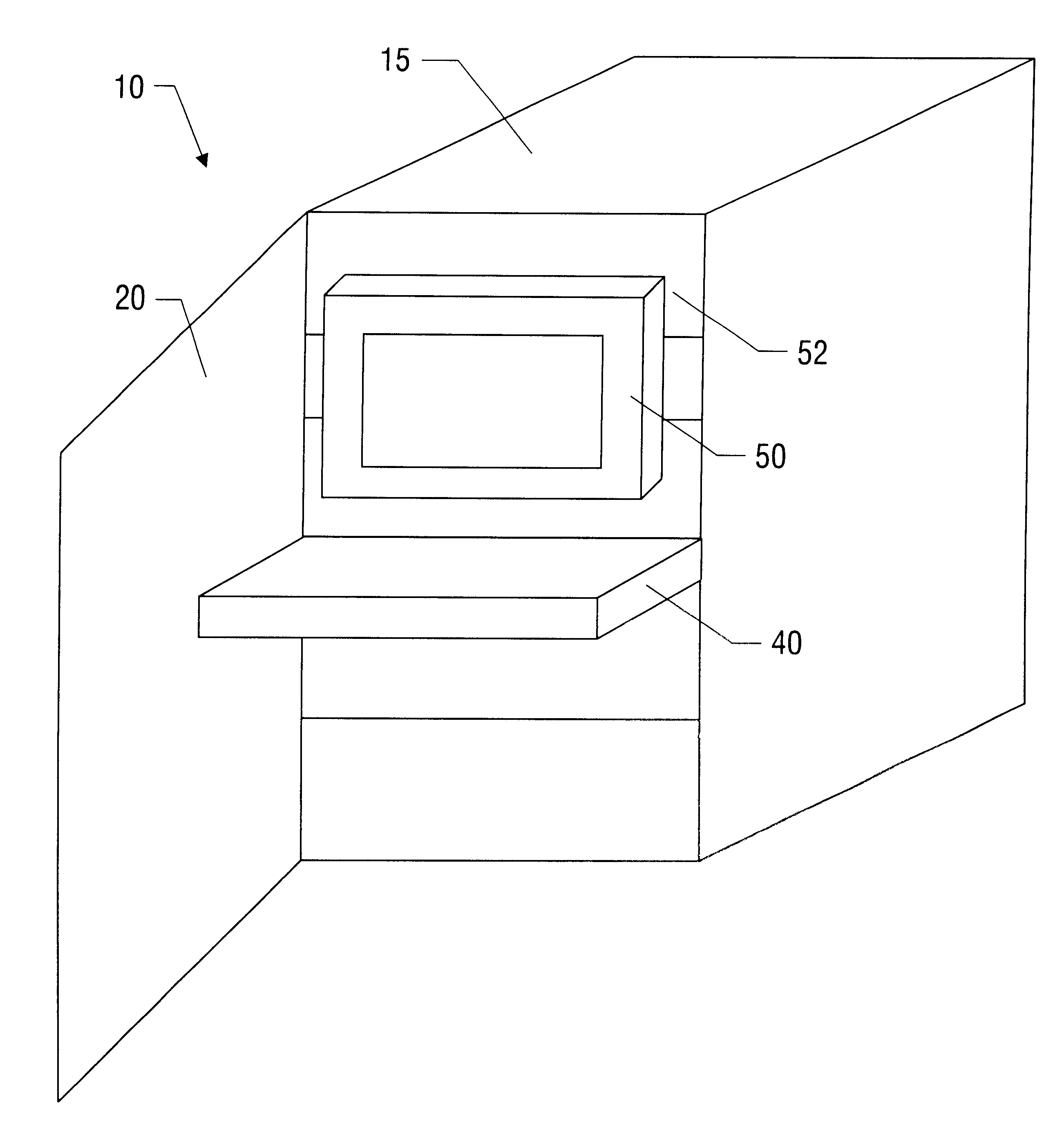
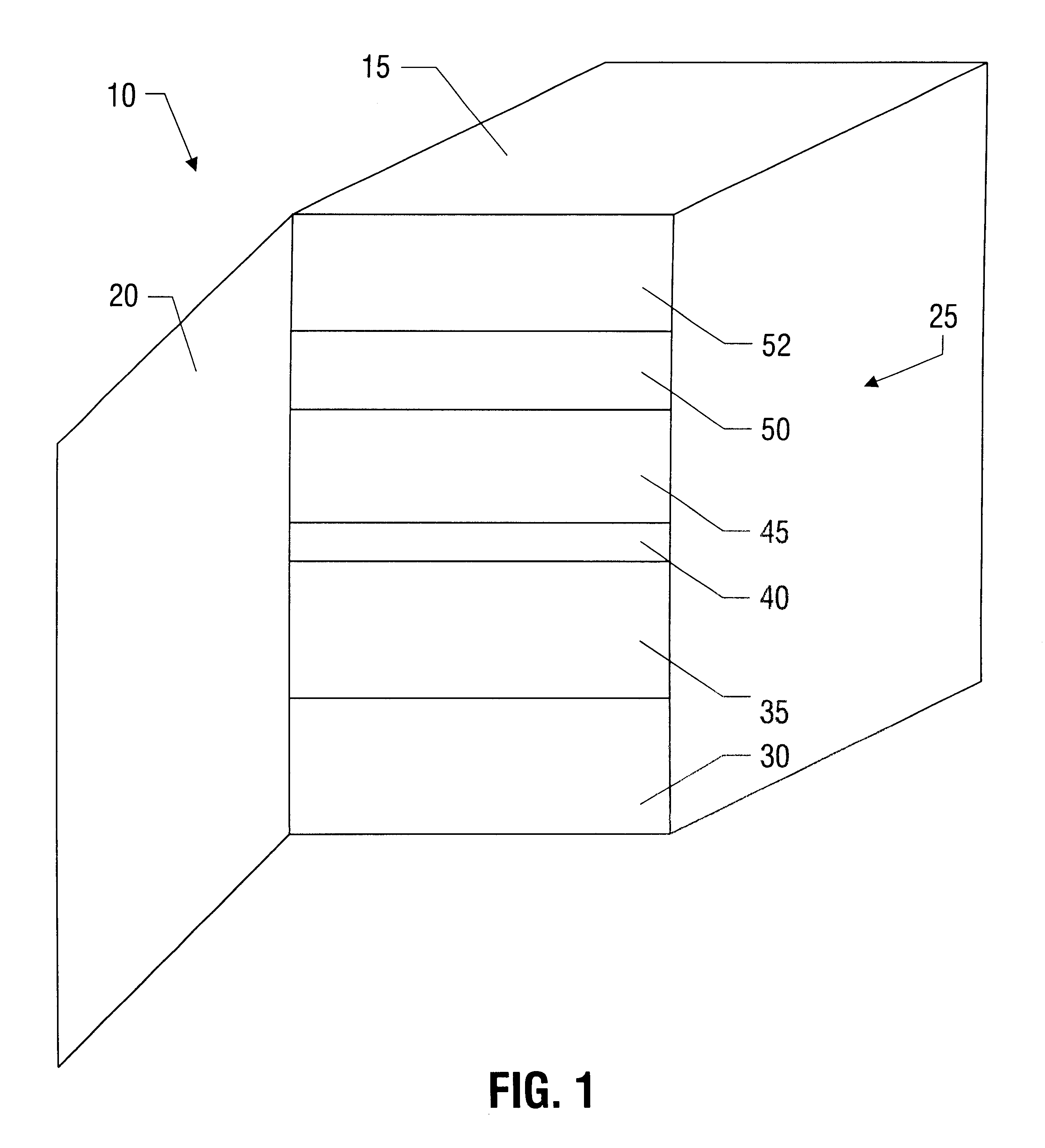
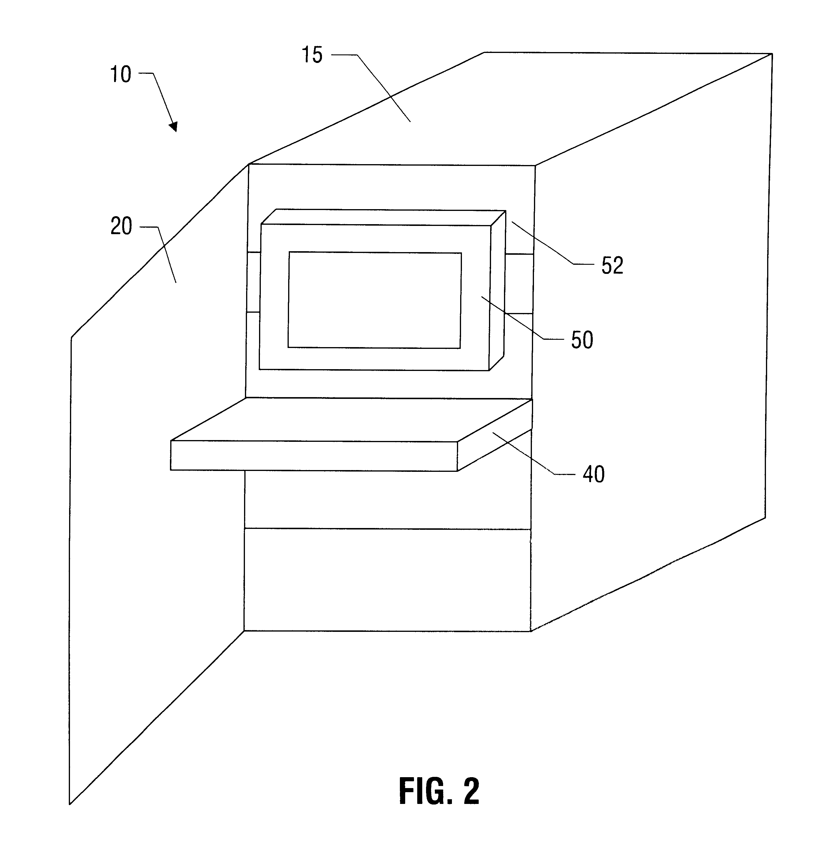
Referring now the figures, and particularly, to FIG. 1, a simplified isometric view of a computer system 10 is provided. The computer system 10 includes a cabinet 15 with a door 20 and a plurality of devices 25. The particular devices 25 employed in the computer system 10 depend on the...


PUM


Abstract

An apparatus for mounting a display includes a tray having an end and a back plate pivotably mounted to the tray proximate the end. An apparatus in accordance with another aspect of the invention includes a cabinet, a pivotable display assembly, and a keyboard assembly. The cabinet has mounting rails. The pivotable display assembly includes a display tray having an end and being mounted to the mounting rails and a back plate pivotably mounted to the tray proximate the end. The keyboard assembly includes a keyboard tray and a keyboard slide having fixed and moveable portions. The fixed portion is mounted to the mounting rails, and the moveable portion is mounted to the keyboard tray. The switchbox is mounted to the fixed portion of the keyboard slide.

Description

1. Field of the InventionThis invention relates generally to mounting systems for displays, and, more particularly, to a pivotable display mounting apparatus suitable for use in a rack system.2. Description of the Related ArtComputer systems typically employ a monitoring system, such as a video display. Certain computer systems use a rack in which multiple devices, such as servers, peripheral devices, etc., are mounted. Often multiple servers are housed in the same rack, and are monitored by selectively coupling a video display, keyboard, and a mouse (or trackball) to one of the servers through a multiplexing unit. The multiplexing unit, commonly referred to as a switchbox, is typically installed in one of the slots in the rack.One technique for providing the monitoring capability involves mounting a conventional monitor on a shelf in the rack unit. Such an arrangement uses a large amount of available rack space, and is thus inefficient if a large number of components are required t...

Claims


Application Information

Patent Timeline
Patent Type & Authority Patents(United States)
IPC IPC(8): G06F1/16G06F3/02H05K7/14
CPCG06F1/16H05K7/1421G06F3/0202G06F1/1601H05K7/1494
Inventor LANDRUM, GARYLITTLE, KRISTINEOWENS, MICHAEL
Owner HEWLETT PACKARD DEV CO LP
Why Eureka
Try Eureka