Bone screw for anchoring a marrow nail

a technology of bone screw and marrow nail, which is applied in the direction of threaded fasteners, osteosynthesis devices, prosthesis, etc., can solve the problems of bone losing its stretch in the proximal region of the screw, and affecting the stability of the screw

Inactive Publication Date: 2002-03-12
ZIMMER GMBH
View PDF18 Cites 267 Cited by
  • Summary
  • Abstract
  • Description
  • Claims
  • Application Information

AI Technical Summary

Problems solved by technology

A through-going screw thread which is intended to support the marrow nail with its middle region has the disadvantage that the bone loses its stretch in the proximal region of the screw due to the large screw-in length.
This means that in the lateral region of the screw the thread is in such a case limited in its shaping in the proximal region by the rupture action of the cylindrical part.
Precisely at this location an undesirable rupture effect can arise, which produces tears in the bone.

Method used


Image

  • Bone screw for anchoring a marrow nail
  • Bone screw for anchoring a marrow nail
  • Bone screw for anchoring a marrow nail

Examples


Embodiment Construction

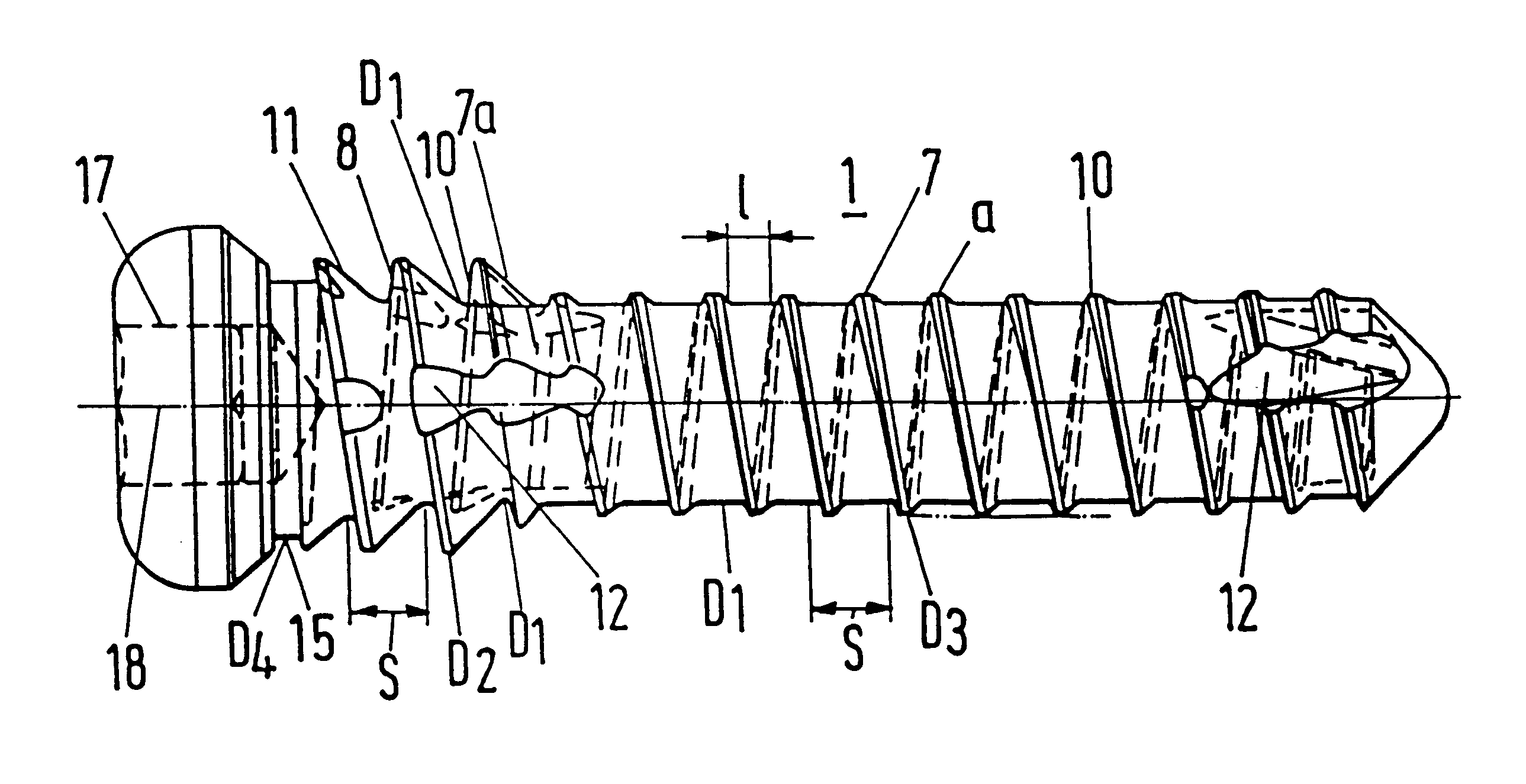
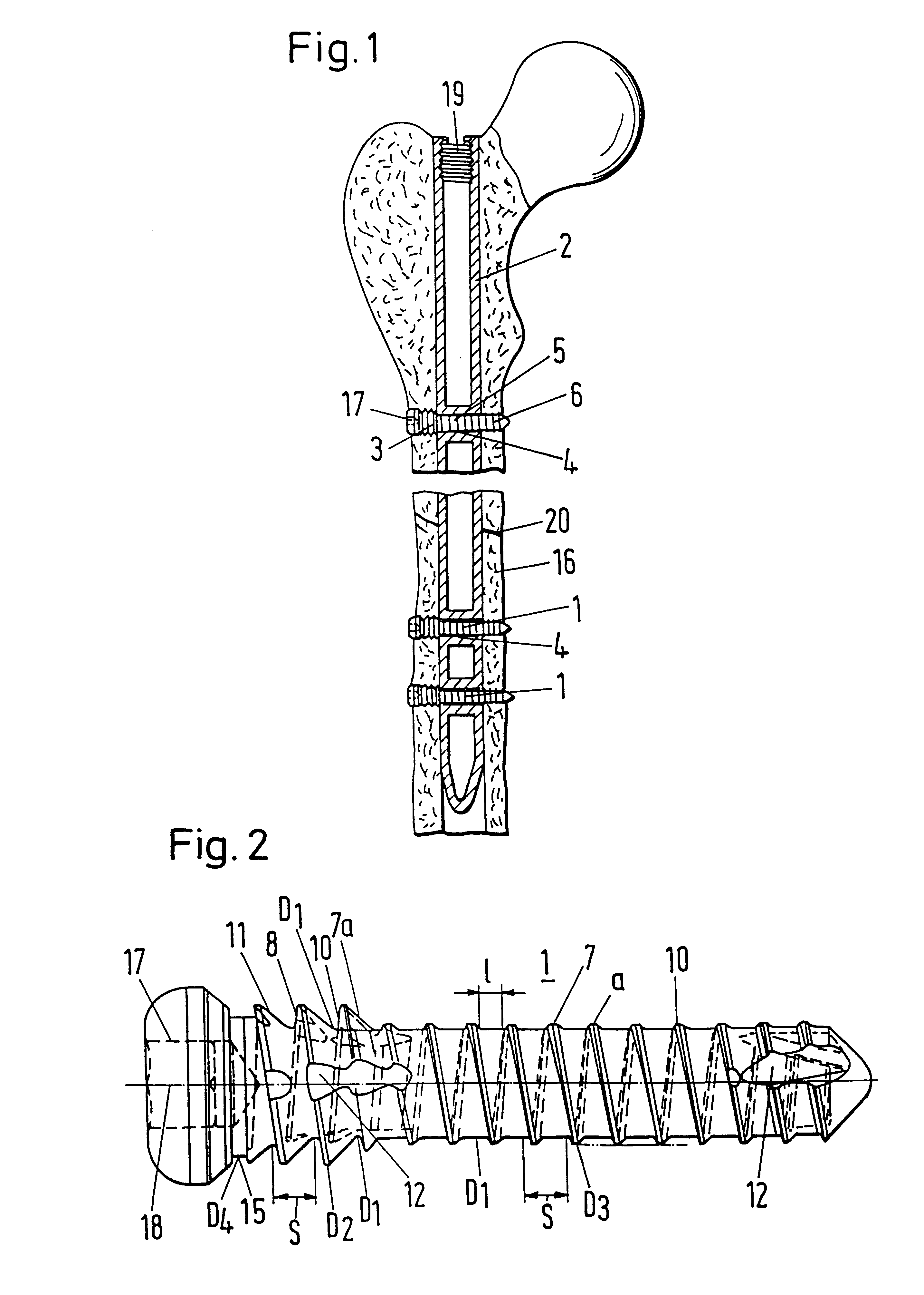
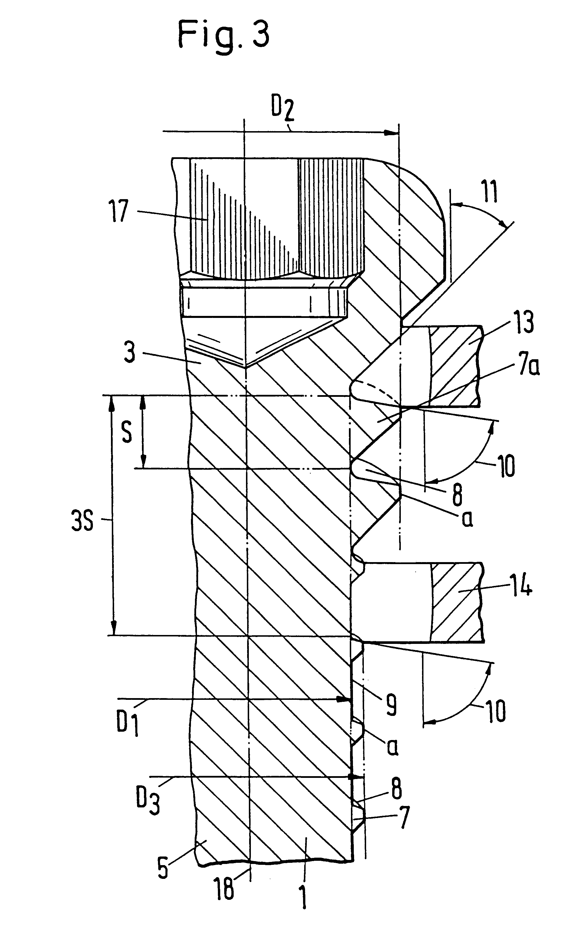
Bone screws 1 for anchoring a marrow nail 2 with transverse bores in a tubular bone are shown in the figures. The bone screws 1 have a thread 7 with a pitch S, with a core diameter D.sub.1 and with outer diameter D.sub.3, which supports the marrow nail with the middle part 5 of the screw and fixes the screw 1 in the bone with the distal part 6, with the thread having a flat cylindrical thread base 9 with a length l>0.3 S. In addition, a second thread 7a with the same pitch S and with the core diameter D.sub.1 is present in the proximal head part 3, however with a greater outer diameter D.sub.2 >D.sub.3 in order proximally to achieve a fixing with a greater thread profile.

In FIG. 1 a marrow nail 2 bridges over a fracture location 20 in a femur bone 16. At both sides of the fracture location 20 the marrow nail 2 has transverse bores 4 which guide bone screws 1, which themselves are fixed distally and proximally in the bone 16 with thread profiles 7, 7a of different sizes and of the sa...


PUM


Abstract

A Bone screw for anchoring a marrow nail with transverse bores in a tubular bone. The bone screw had a thread with a pitch S, a core diameter D1 and outer diameter D3. The screw supports the marrow nail with a middle part and is fixed in the bone with a distal part. The thread has a flat cylindrical thread base with a length l>0.3 S. In addition, a second thread with the same pitch S and with the core diameter D1 is present in a proximal head part, but has a greater outer diameter D2>D3 in order to proximally achieve a fixing with a greater thread profile.

Description

1. Field of the InventionThe invention relates to a bone screw for anchoring a marrow nail.2. Description of the Prior ArtMarrow nails are used for the support of fractures at tubular bones. As a rule marrow nails are hammered into the marrow chamber in order to provide the bone with an orientation in the longitudinal direction and subsequently to effect an additional anchoring of the marrow nail in the tubular bone with screw-like anchoring elements, which are passed through transverse bores in the marrow nail.In U.S. Pat. No. 4,622,959 a marrow nail is shown which is connected to an aiming device at its proximal end after its hammering in into the femur bone, in order to pre-bore the tubular bone in alignment with its existng transverse bores and subsequently to turn in anchoring screws which are supported with their thread at both sides by the marrow nail.Anchoring pins and screws for marrow nails are also shown in the layering open print DE-A-32 44 243 and in the German utility ...

Claims


Application Information

Patent Timeline
Patent Type & Authority Patents(United States)
IPC IPC(8): A61B17/68A61B17/72A61B17/86
CPCA61B17/863A61B17/72
Inventor ADAM, MICHAEL
Owner ZIMMER GMBH
Why Eureka
Try Eureka