Spinal fixation system having locking and unlocking devices for use with a multi-planar, taper lock screw

a multi-planar, taper lock screw technology, applied in the field of orthopaedic surgery, can solve the problems of reducing nerve function, and affecting the operation efficiency of the spinal rod, and achieve the effect of convenient operation

Active Publication Date: 2007-04-26
K2M
View PDF20 Cites 298 Cited by
  • Summary
  • Abstract
  • Description
  • Claims
  • Application Information

AI Technical Summary

Benefits of technology

[0016] The present system provides novel component devices and a method for selectively locking and unlocking a spinal rod to a bone screw usin

Problems solved by technology

Persons suffering from any of the above conditions typically experience extreme or debilitating pain and often times diminished nerve function.
Many conventional devices for locking a spinal rod to a fixation hook or screw do not offer the needed variability to allow the spinal rod to be easily connected to adjacent vertebrae, which are not aligned on the same plane.
In recent years some effort has been made to provide taper lock bone screws and further to provide taper lock bone screws that are multi-planar; however, even when multi-planar type bone screws have been developed, the use of those screws has proven difficult because the locking and unlocking instruments that are used by the surgeon during the surgical procedure are of a generic design and inadequate to quickly lock or unlock the bone screws.
Such torsional forces can alter the disposition of the screw in the bone or can damage the bone, which may be of poor strength or quality in patients undergoing surgery.
As such, the torsional forces can adversely affect the outcome of the procedure.
Conventional efforts to meet this need have fallen short in that no systematic approach has been provided that adapts the spinal rod to the multi-planar

Method used


Image

  • Spinal fixation system having locking and unlocking devices for use with a multi-planar, taper lock screw
  • Spinal fixation system having locking and unlocking devices for use with a multi-planar, taper lock screw
  • Spinal fixation system having locking and unlocking devices for use with a multi-planar, taper lock screw

Examples


Embodiment Construction

[0042] Detailed embodiments are disclosed herein; however, it is understood that the following description is provided as being exemplary of the invention, which may be embodied in various forms without departing from the scope of the claimed invention. Thus, the specific structural and functional details provided in the description are non-limiting, but serve merely as a basis for the invention defined by the claims provided herewith.

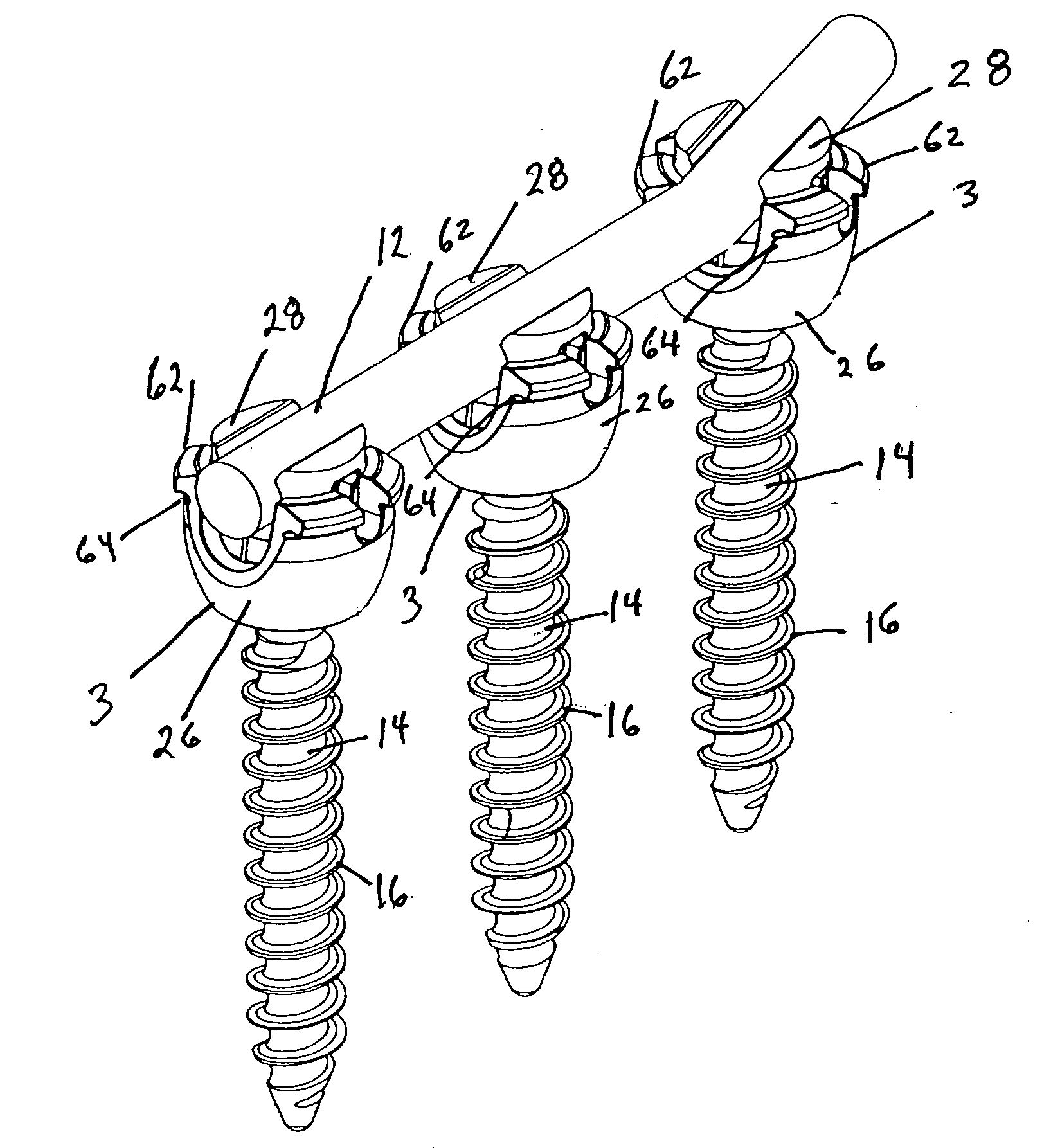
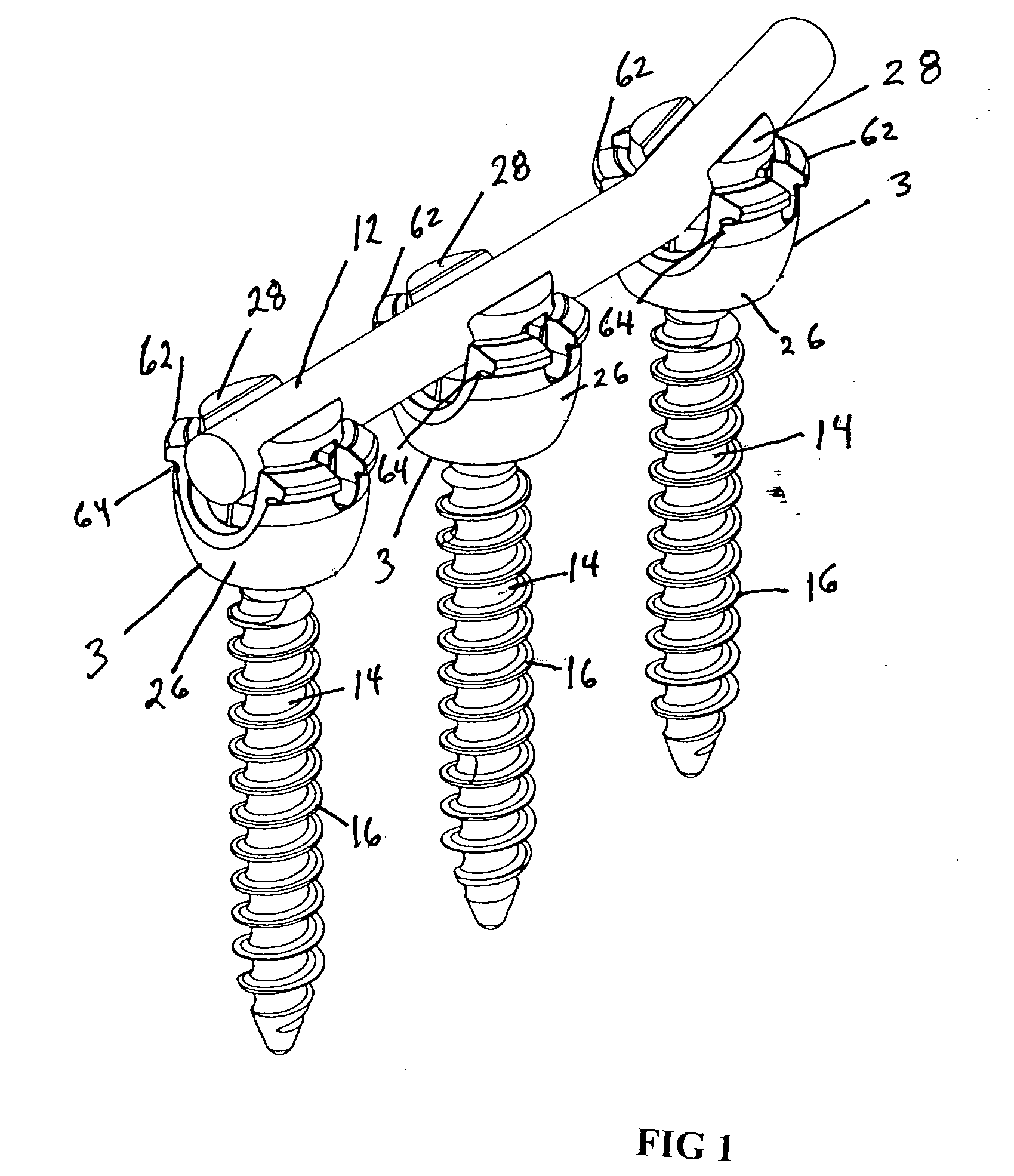
[0043]FIG. 1 illustrates an example of a unilateral orthopedic fixation assembly that includes a connecting rod 12 and three separate screw components 3. In the example shown, the connecting rod 12 is a spinal rod having a generally circular cross section; however, it is within the concept of the invention to secure connecting rods of any suitable cross-sectional configuration required for the need at hand.

[0044] The System.

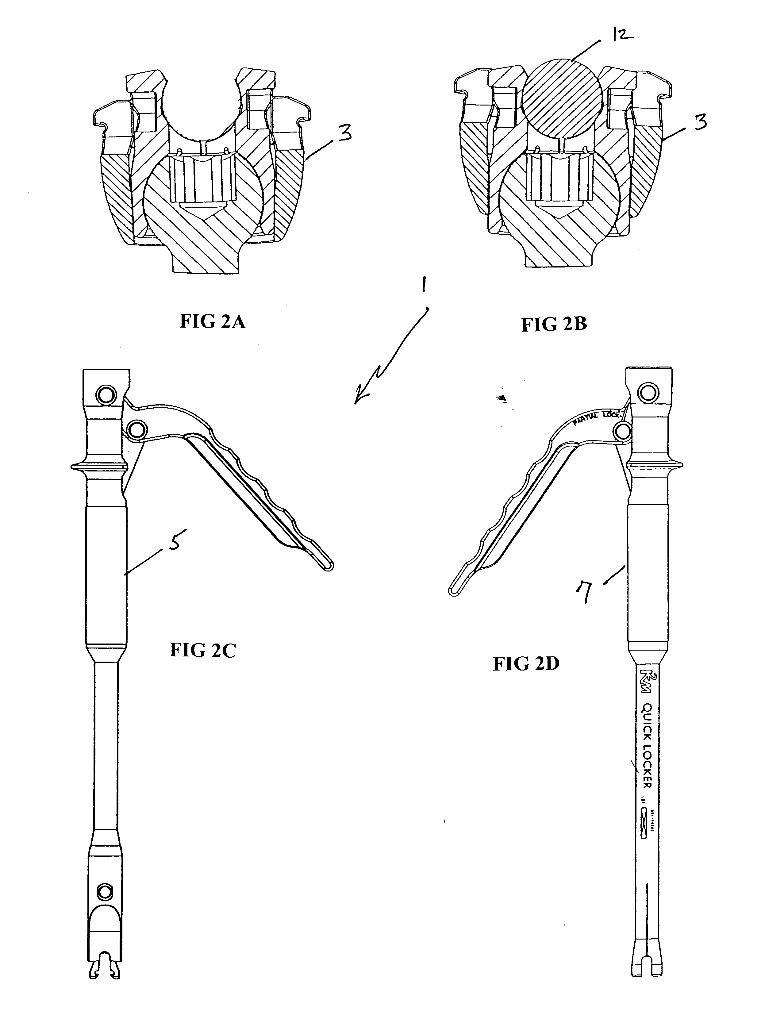
[0045] The novel spinal fixation system is generally shown at 1 in FIGS. 2A-D. FIG. 2A shows the screw component of the system ...


PUM


Abstract

Provided is a novel spinal fixation system that includes a novel multi-planar taper lock screw for connecting a connecting rod to bone as well as a novel locking device and a novel unlocking device, each being configured to selectively partially lock or fully the novel screw of the system. The screw is capable of multi-directional articulation while the connecting rod position can remain stable and aligned as needed. After the screw had been articulated and properly positioned, it can be locked such that the screw and the connecting rod will remain in relative position to the bone. The screw is configured for easy insertion and connection as well as easy removal and disconnection from the connecting rod. A method of fixing bones or bone fragments using the novel system is also provided.

Description

BACKGROUND [0001] 1. Technical Field [0002] The present invention relates to orthopedic surgery, and in particular to devices for stabilizing and fixing the bones and joints of the body. Particularly, the present invention relates to a spinal fixation system that includes surgical instruments that can be used for locking or unlocking a taper lock screw, the screw preferably being multi-planar and useful for securing a spinal rod or plate to a vertebra. [0003] 2. Background Art [0004] The spinal column is a complex system of bones and connective tissues that provides support for the human body and protection for the spinal cord and nerves. The adult spine is comprised of 24 vertebral bodies, which are subdivided into three areas including seven cervical vertebrae, 12 thoracic vertebrae and five lumbar vertebrae. Between each vertebral body is an intervertebral disc that cushions and dampens the various translational and rotational forces exerted on the spinal column. [0005] There are...

Claims


Application Information

Patent Timeline
IPC IPC(8): A61F2/30
CPCA61B17/7011A61B17/7032A61B17/861A61B17/7037A61B17/7086A61B17/7035
Inventor BARRUS, MICHAELJONES, SCOTT A.STRAUSS, KEVIN R.
Owner K2M
Why Eureka
Try Eureka