Helical reverse angle guide and advancement structure with break-off extensions

a reverse angle and helical guide technology, applied in the direction of prosthesis, instruments, gearing, etc., can solve the problems of premature break-off of such extensions, inability to successfully equip extensions with v-threads, etc., and achieve the effect of improving helical guide and advancement structure, low profile implants, and economical manufacturing

Inactive Publication Date: 2006-02-02
JACKSON
View PDF47 Cites 314 Cited by
  • Summary
  • Abstract
  • Description
  • Claims
  • Application Information

AI Technical Summary

Problems solved by technology

Because of the flimsy or weakened nature of such extensions, it would not even be feasible to successfully equip extensions with V-threads, not only because of the potential for outward splaying of the extensions as force is applied to the rod by the closure member, but also because of the potential that such splaying would cause premature break-off of such extensions.

Method used


Image

  • Helical reverse angle guide and advancement structure with break-off extensions
  • Helical reverse angle guide and advancement structure with break-off extensions
  • Helical reverse angle guide and advancement structure with break-off extensions

Examples


Embodiment Construction

[0027] As required, detailed embodiments of the present invention are disclosed herein; however, it is to be understood that the disclosed embodiments are merely exemplary of the invention, which may be embodied in various forms. Therefore, specific structural and functional details disclosed herein are not to be interpreted as limiting, but merely as a basis for the claims and as a representative basis for teaching one skilled in the art to variously employ the present invention in virtually any appropriately detailed structure.

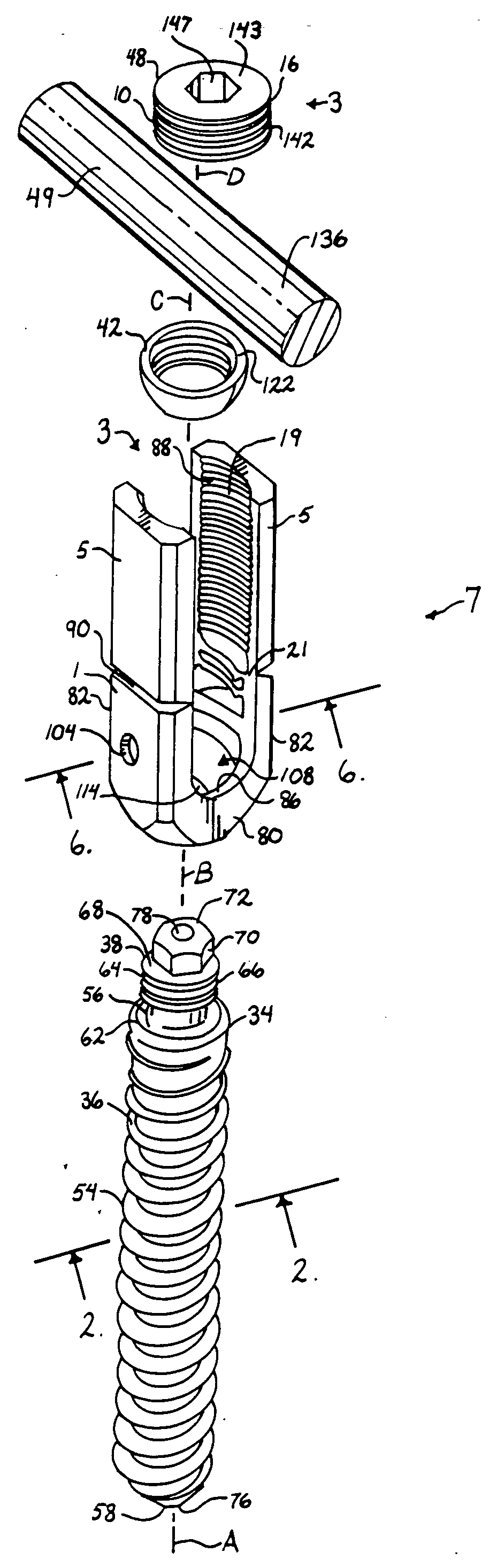
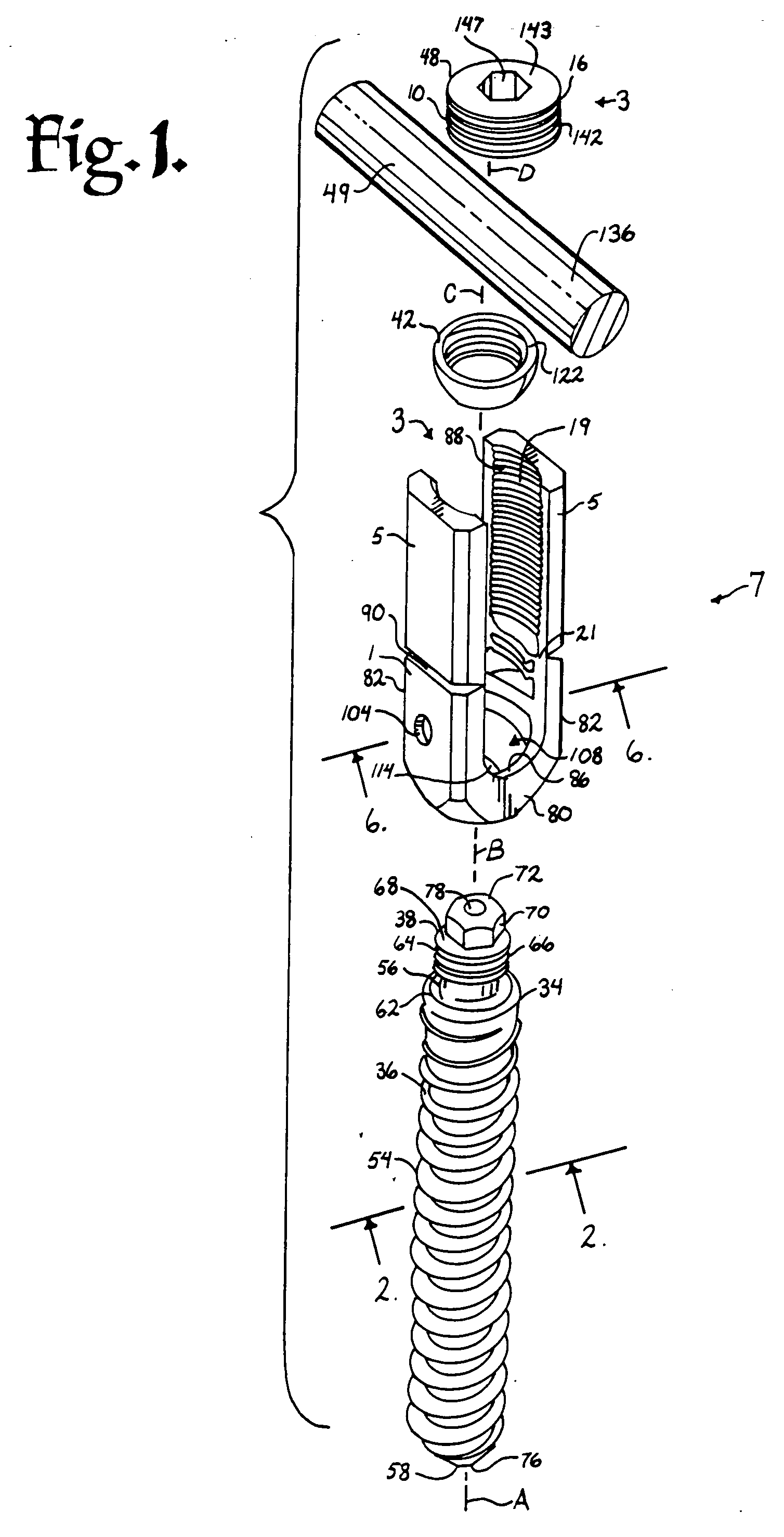
[0028] Referring to the drawings in more detail, the reference numeral 1 designates a receiver according to the invention having a component of a helical guide and advancement reverse angle structure, generally 3, in combination with upwardly extending break-off tabs or extensions 5 used in conjunction with a medical implant assembly, generally 7, that embodies the present invention. It is noted that any reference to the words top, bottom, up and down, and ...


PUM


Abstract

A spinal fixation device combines an anchor member with an open receiver, such as a polyaxial bone screw or a hook, with a rotatable closure that operably clamps a spinal fixation rod to the anchor member. The anchor member has spaced apart arms forming a rod receiving channel. The arms have arm extensions or tabs connected to main portions of the arms by weakened regions to enable the extensions to be broken off or separated after the rod is clamped. The closure and inner surfaces of the arms and tabs have mating helical, anti-splay, reverse angle guide and advancement structure formed thereon that mechanically cooperate to prevent splaying of the arms and the extensions as the closure is advanced into the rod receiving channel. The increased length of the arms with the extensions enables the rod to be captured at a greater distance from the seat of the channel and allows the rod to be urged toward the seat by helical advancement of the closure into the channel, starting between the extensions. Separation of the break-off extensions results in an implant with a desirable low profile.

Description

CROSS-REFERENCE TO RELATED APPLICATIONS [0001] This application claims the benefit of U.S. Provisional Application Ser. No. 60 / 627,000 filed Nov. 10, 2004, and is a continuation-in-part of U.S. patent application Ser. No. 10 / 986,377 filed Nov. 10, 2004, and also is a continuation-in-part of U.S. patent application Ser. No. 09 / 644,777 filed Aug. 23, 2000.BACKGROUND OF THE INVENTION [0002] The present invention relates to improvements in interlocking or interconnecting helical guide and advancement structures such as reverse angle thread forms and helical flanges and, more particularly, to mating helical guide and advancement arrangements providing anti-splay interconnection when radial loading or engagement occurs. Such guide and advancement structures with anti-splay contours are particularly advantageous when used in combination with open headed bone screws formed with extended arms or tabs to facilitate the capture and reduction of spinal fixation rods, after which the arm extensi...

Claims


Application Information

Patent Timeline
Patent Type & Authority Applications(United States)
IPC IPC(8): A61F2/30
CPCA61B17/7032A61B17/7037Y10T74/22A61B2019/307A61B17/864A61B2090/037
Inventor JACKSON, ROGER P.
Owner JACKSON
Why Eureka
Try Eureka