Vibration damping device

Inactive Publication Date: 2002-03-19
ZF FRIEDRICHSHAFEN AG
View PDF25 Cites 25 Cited by
  • Summary
  • Abstract
  • Description
  • Claims
  • Application Information

AI Technical Summary

Benefits of technology

The deflection areas proceed from the vertex area in substantially opposite axial directions. According to this embodiment, the deflection path extends substantially in the axial direction. The deflection area proceeding in the axial direction curves toward the axis of rotation of the base body. Therefore, the deflection mass moves substantially in a plane containing the axis of rotation. This movement of the deflection mass is substantially orthogonal to the movement direction of commonly known deflection masses and may be used to damp or eliminate wobbling excitations of the rotatable base body.
By providing different masses or mass moments of inertia in a plurality of deflection masses, each of these different deflection masses forms an oscillator with a different natural frequency. In this way, different excitations occurring in the rotating system at different frequencies may be simultaneously reduced.
The damping behavior of an oscillator of this kind may also be influenced in that the oscillating mass is compulsorily held in a determined position, i.e., can only execute a defined movement, and is stabilized in other directions. This especially prevents unwanted and undefined frictional contact with other components. According to another feature of the present invention, this result may be achieved in that the at least one deflection mass and the associated deflection path have a mutual contact profile such that the at least one deflection mass is stabilized in its position essentially in a plane containing the deflection path.
For stabilizing the movement of the deflection mass, two oppositely arranged guide axles with associated guide paths may be arranged at the at least one deflection mass.

Problems solved by technology

However, a problem with these prior art devices occurs when additional vibrational excitations occur, especially vibrational excitations of a different frequency or type.
Such wobbling movements also occur at certain frequencies and may impair the drive system.
As a result, a considerable proportion of rotational energy is changed in a defined manner into the moving deflection mass, which results in a corresponding damping or eradicating behavior.

Method used


Image

  • Vibration damping device
  • Vibration damping device
  • Vibration damping device

Examples


first embodiment

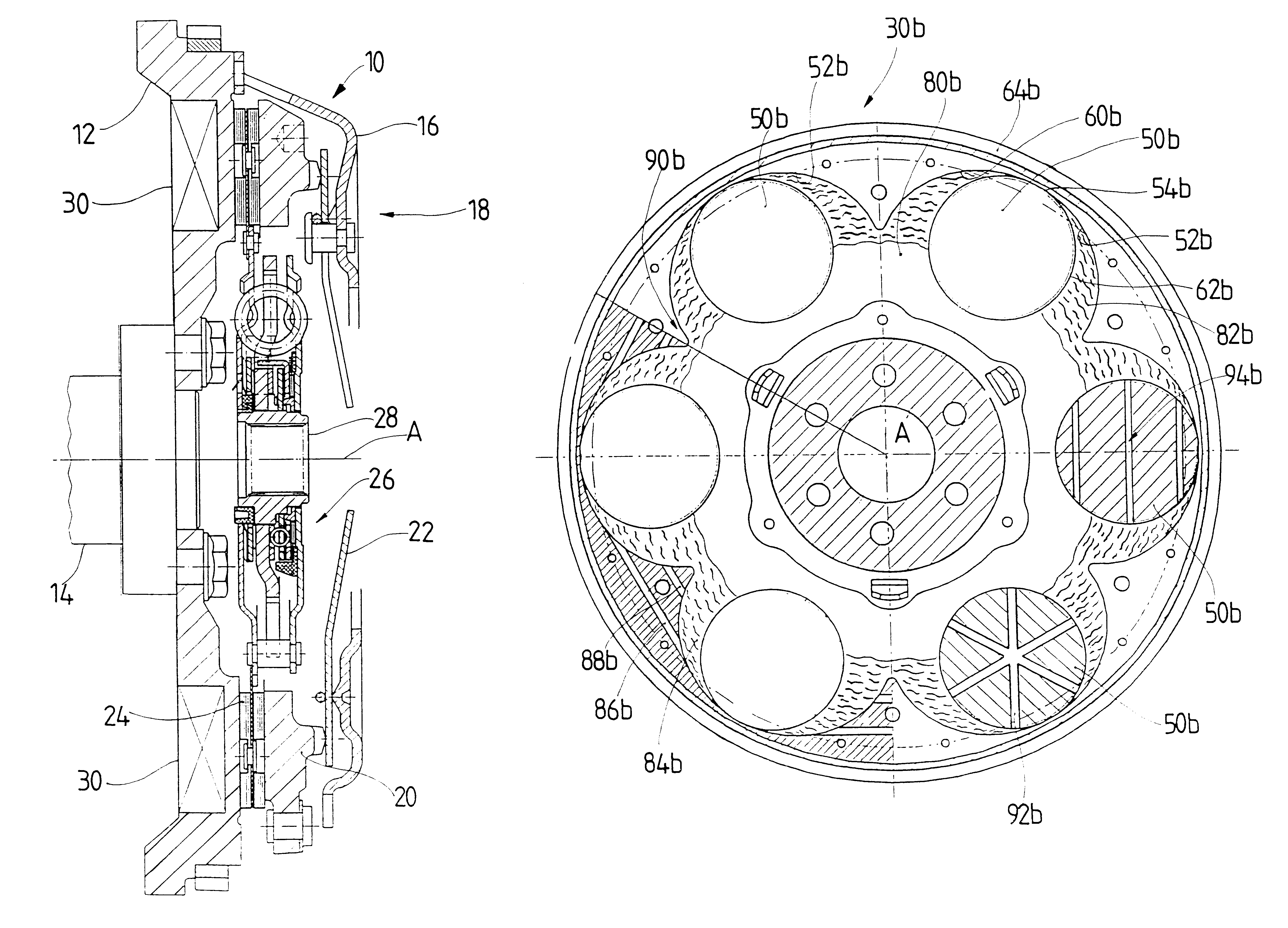
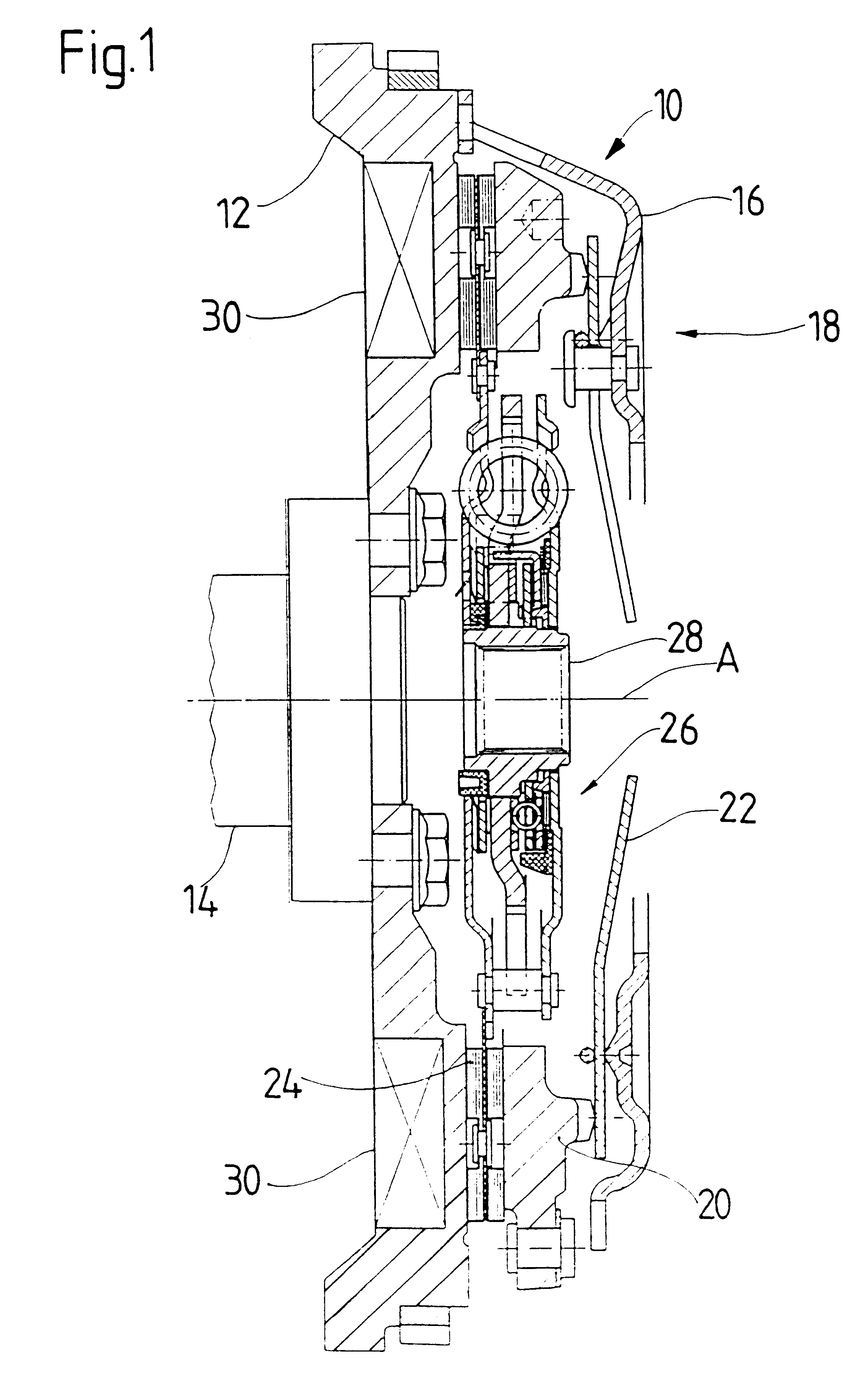
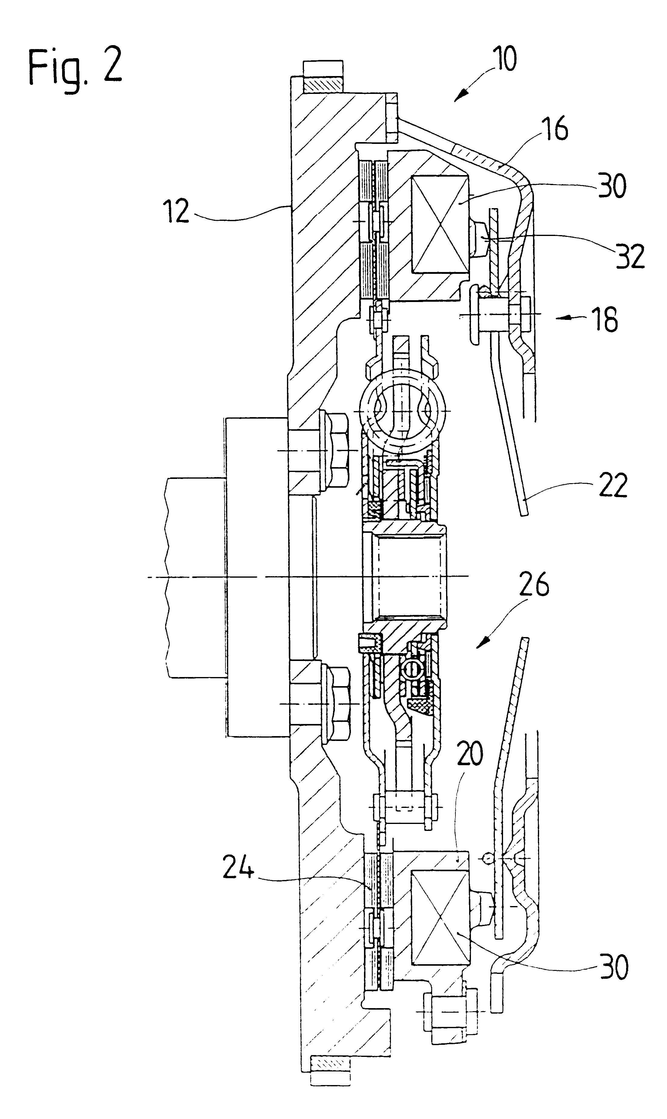
FIGS. 5-7 show the above-described vibration damping device 30.

embodiment form

the vibration damper 30 shown in FIGS. 5-7 may be used for damping torsional vibrations arising, for example, from irregular vibrational excitation caused by ignition explosions in an internal combustion engine and for the damping of vibrations excited by wobbling movements. For this purpose, as is shown in FIG. 5, six individual deflection masses 50 which have a spherical shape in the present instance are distributed along a circumference. A deflection path 52 having a three-dimensional curved surface in the present embodiment form is associated with each deflection mass 50. Referring now also to FIG. 6, each of the deflection paths 52 of the deflection bodies 50 has a vertex area 54 in a radial outer region. Furthermore, deflection areas 56, 58 proceed from this vertex area 54 in opposite directions and in a plane containing the axis of rotation A. These deflection areas 56, 58 are curved so that they increasingly approach the axis of rotation A as their distance from the vertex a...


PUM


Abstract

A vibration damping device for a drive system of a motor vehicle includes a base body rotatable about an axis of rotation (A) and a deflection mass arrangement arranged in the base body having at least one deflection mass and a deflection path associated with the at least one deflection mass and along which the at least one deflection mass is movable during rotation of the base body about the axis of rotation. The deflection path has a vertex area and deflection areas emanating from the vertex area in opposite directions. The deflection areas proceed from the vertex area in substantially opposite axial directions.

Description

1. Field of the InventionThe present invention is directed to a vibration damping device for a drive system of a motor vehicle having a base body arranged for rotating about an axis of rotation and a deflection mass arrangement arranged in the base body and having at least one deflection mass and a deflection path associated with the at least one deflection mass and along which the deflection mass is movable during rotation of the base body about the axis of rotation, the deflection path having a vertex area and deflection areas proceeding in opposite directions from the vertex area.2. Description of the Related ArtA vibration damping device is disclosed in German reference DE 44 26 317 A1 having a plurality of deflection paths arranged in a base body and distributed about an axis of rotation of the base body. Deflection masses arranged in the base body are movable along these deflection paths which extend in the circumferential direction from vertex areas and curved toward the axis...

Claims


Application Information

Patent Timeline
IPC IPC(8): F16F15/10F16F15/134F16F15/14F16F15/131F16D13/70F16F15/173F16F15/30F16F15/31
CPCF16F15/14F16F15/134
Inventor CARLSON, CORAPEINEMANN, BERNDWETH, JURGEN
Owner ZF FRIEDRICHSHAFEN AG
Why Eureka
Try Eureka