Connector with a side retainer

a technology of side retainers and connectors, which is applied in the direction of coupling bases/cases, coupling device connections, and securing/insulating coupling contact members. it is difficult to make side retainers water-proof, and the number of components is increasing

Inactive Publication Date: 2002-03-26
SUMITOMO WIRING SYST LTD
View PDF16 Cites 42 Cited by
  • Summary
  • Abstract
  • Description
  • Claims
  • Application Information

AI Technical Summary

Problems solved by technology

This makes this type unsuitable for water-proofing, and it has accordingly been difficult to make side retainers water-proof.
However, in the connector described above, a specialised rubber gasket is necessary and, consequently. there is the problem that both the number of components and costs increase.
Moreover the rubber gasket must be attached to a small comp...

Method used


Image

  • Connector with a side retainer
  • Connector with a side retainer
  • Connector with a side retainer

Examples


Embodiment Construction

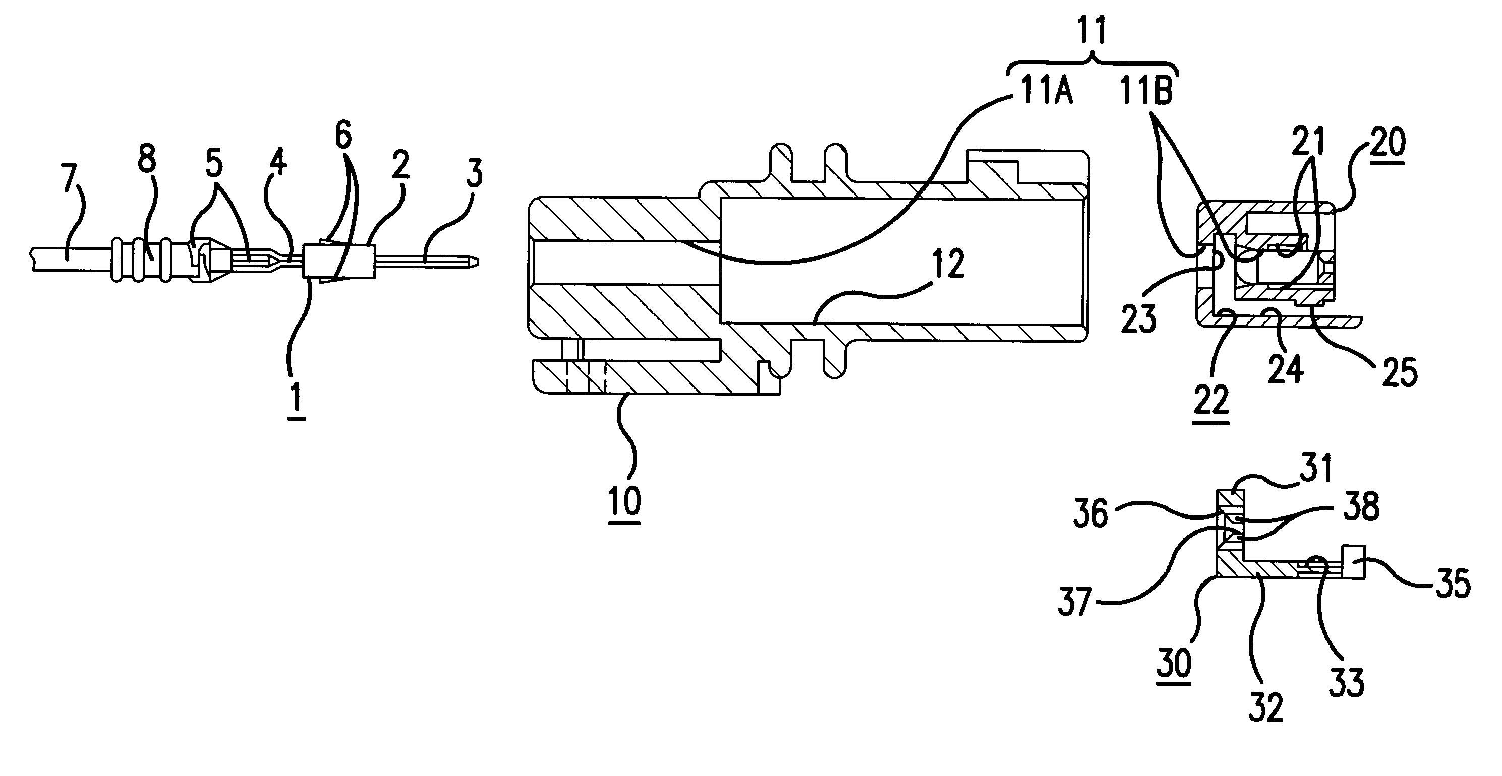
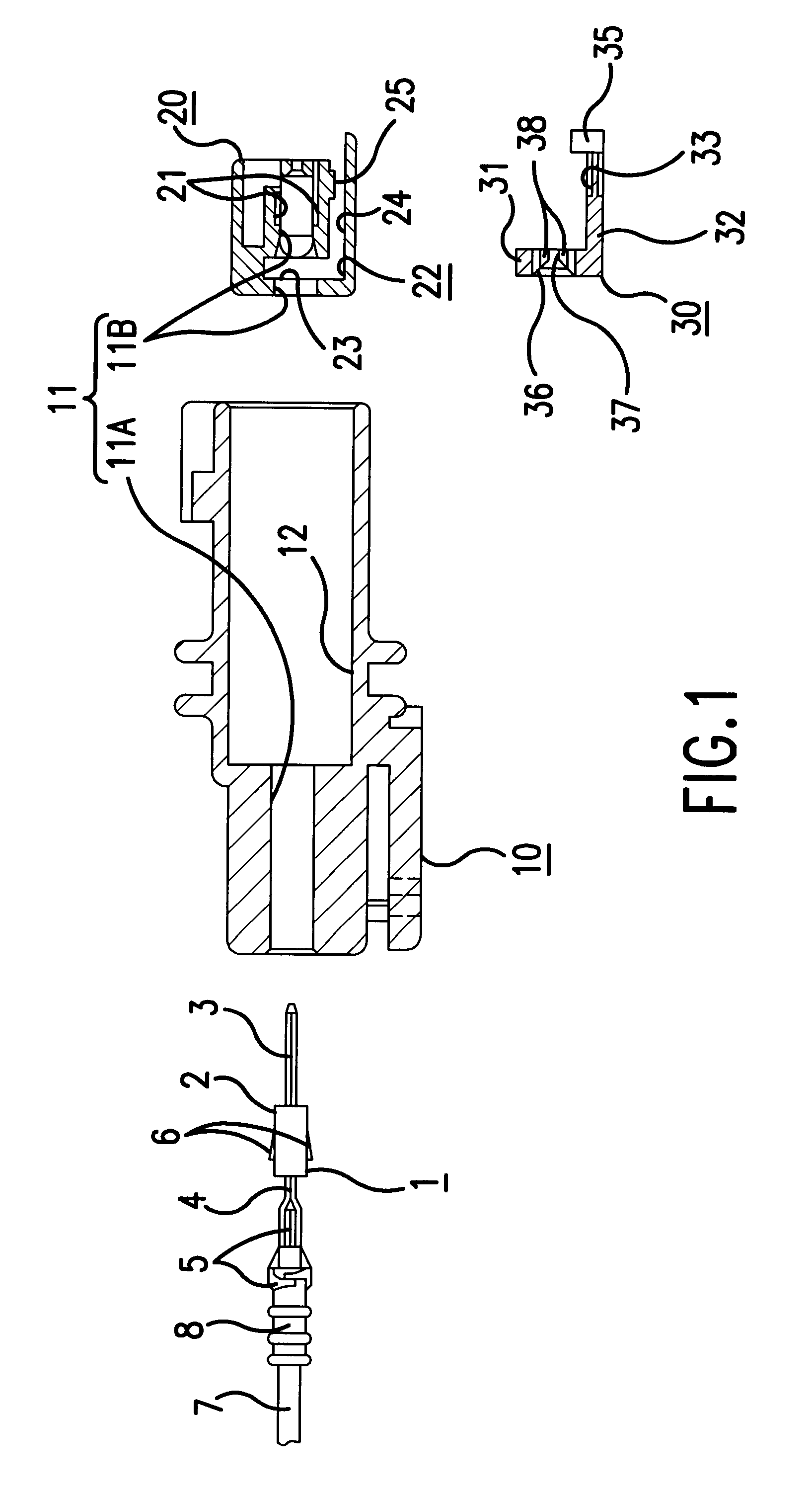
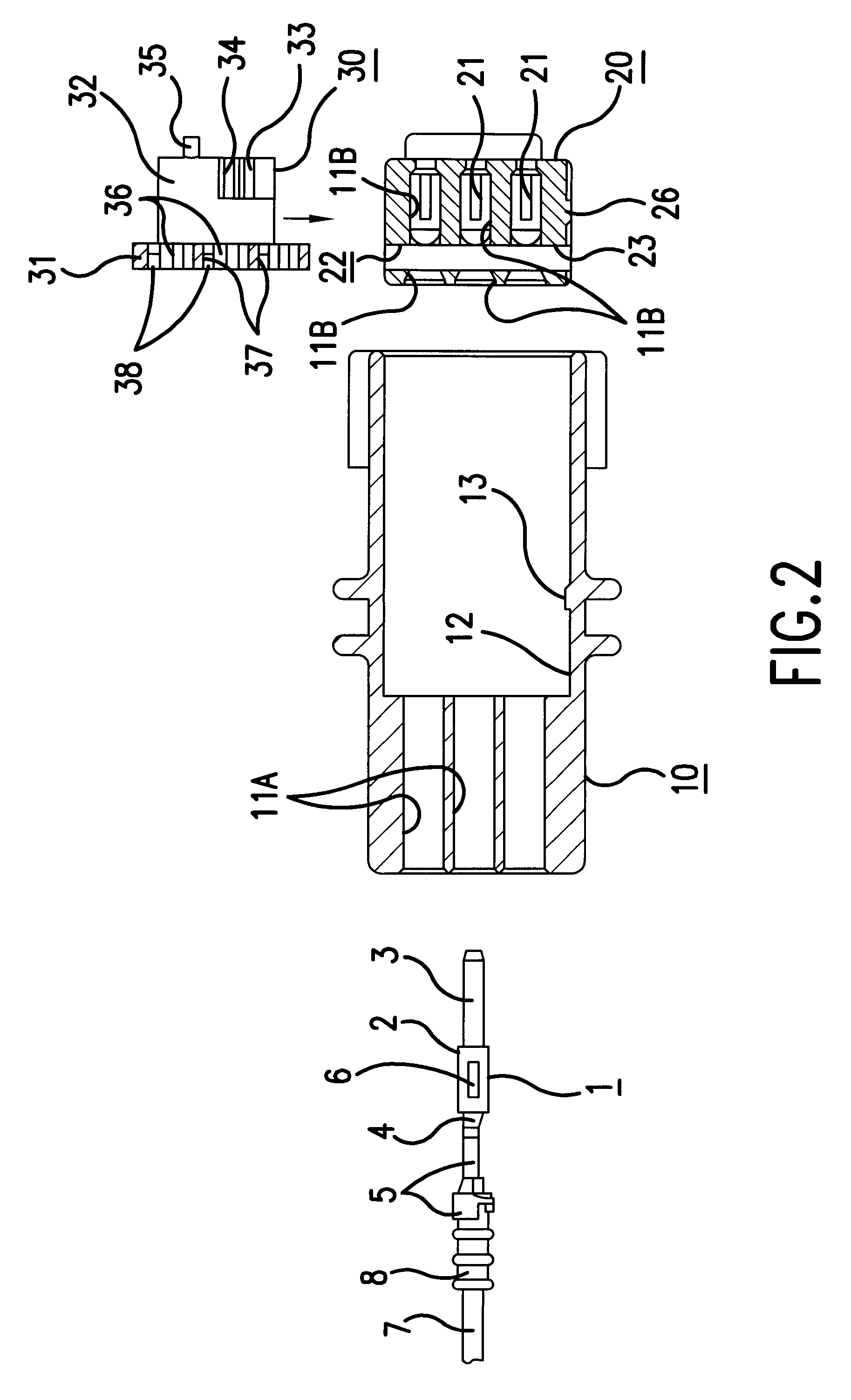
An embodiment of the present invention is described below with the aid of FIGS. 1 to 9. In this embodiment, a male water-proof connector is shown. As shown in FIGS. 1 and 2, this connector comprises an outer housing 10, an inner housing 20 attached to this outer housing 10, a side retainer 30 capable of being attached to the inner housing 20, and male terminal fittings 1 being housing within cavities 11 which extend from the housing 10 to a housing 20 (see FIG. 4).

Each male terminal fitting 1 comprises a box shaped main body 2, and a tab or pin 3 protruding from an anterior tip thereof, the tab being capable of joining with a corresponding female terminal fitting. A joining member 4 protrudes from a posterior tip of the main body 2, and a barrel member 5 is formed on the posterior of this joining member 4, an end portion of an electric wire 7 being attached thereto by crimping. Cantilevered lances 6 at upper and lower wall sides of the main body 2 protrude outwards, the base ends of...


PUM


Abstract

The invention provides a connector with a housing having a simple configuration. After an L-shaped side retainer 30 has been fitted in a temporary stopping position within an opening groove 22 of an inner housing 20, this inner housing 20 is inserted from an anterior direction into a fitting channel 12 of an outer housing 10. A locking protrusion 13 provided in the fitting channel 12 engages a locking member 26 of the inner housing 20, and the inner housing 20 is thereby attached. When the side retainer 30 is to be moved from the temporary stopping position to a main stopping position in which male terminal fittings 1 can be retained, a jig or the like is inserted into the fitting channel 12 to move an operating member 35 formed on an anterior edge of the side retainer 30.

Description

The present invention relates to a connector provided with a side retainer.BACKGROUND TO THE INVENTIONOne type of electrical connector is provided with a side retainer, in which a retainer is inserted into a housing from a side face thereof and retains terminal fittings. In this type of connector the terminal fittings are retained directly, and it therefore has the advantage of having a strong stopping force. However, side retainers must have an opening into the side face of the housing to allow the insertion of the retainer. This makes this type unsuitable for water-proofing, and it has accordingly been difficult to make side retainers water-proof.A connector has been proposed in JP-61-162970 to solve this problem. This has a configuration whereby a separate rubber gasket is attached to an insertion hole of the side retainer, providing the insertion hole with a seal.However, in the connector described above, a specialised rubber gasket is necessary and, consequently. there is the p...

Claims


Application Information

Patent Timeline
IPC IPC(8): H01R13/436H01R13/52H01R13/42
CPCH01R13/4364
Inventor KONOYA, HISASHINAKAMURA, HIDETO
Owner SUMITOMO WIRING SYST LTD
Why Eureka
Try Eureka