

Motorcycle transmission
a technology for motorcycles and transmissions, applied in the direction of gears, cycle equipments, guards, etc., can solve the problems of slipping of flexible drive components, unstable connection between pulleys and drive components, undue noise and unnecessary wear of flexible drive components and slapped components
- Summary
- Abstract
- Description
- Claims
- Application Information
AI Technical Summary
Benefits of technology
Problems solved by technology
Method used
Image

Examples
Embodiment Construction
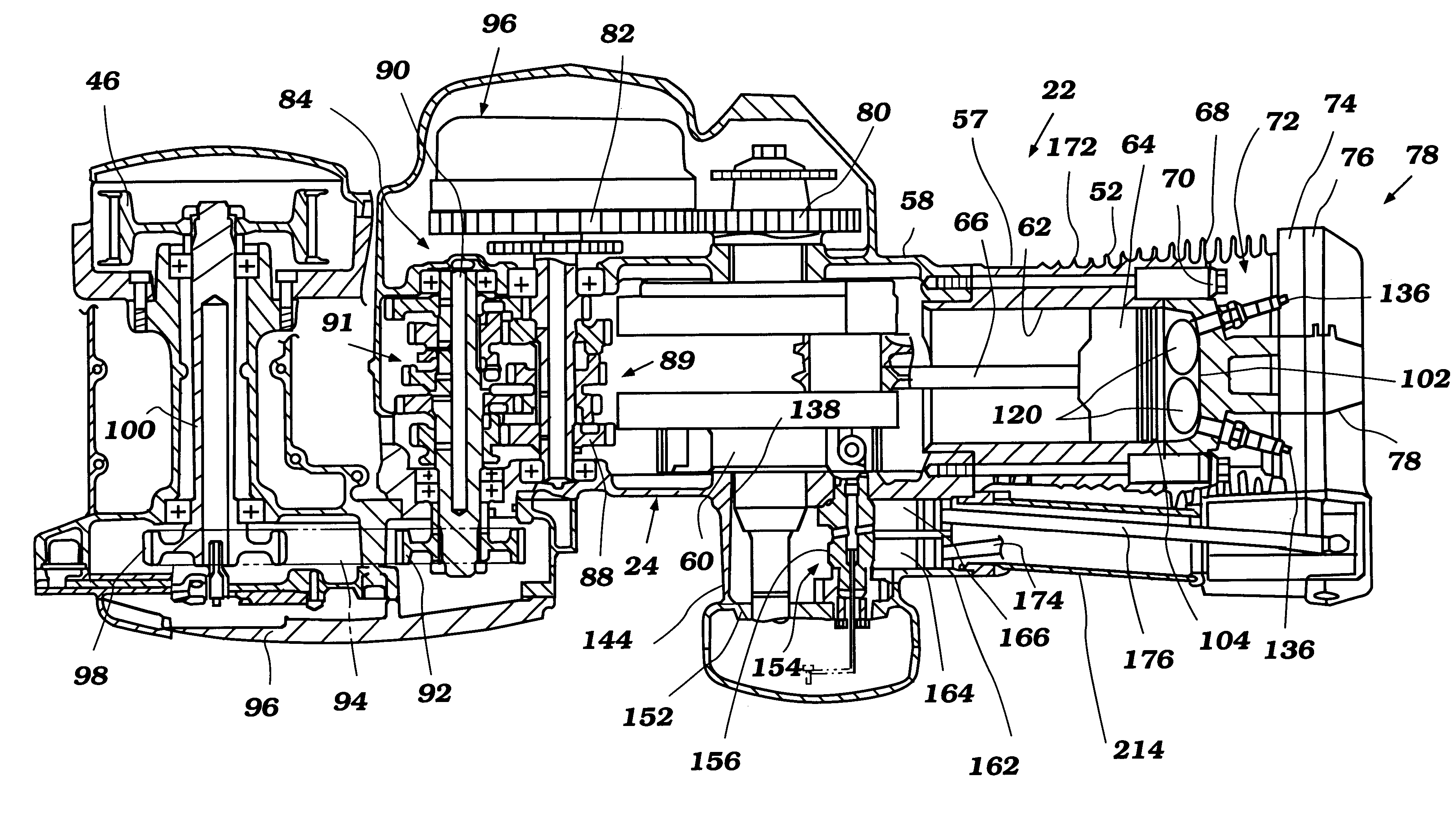
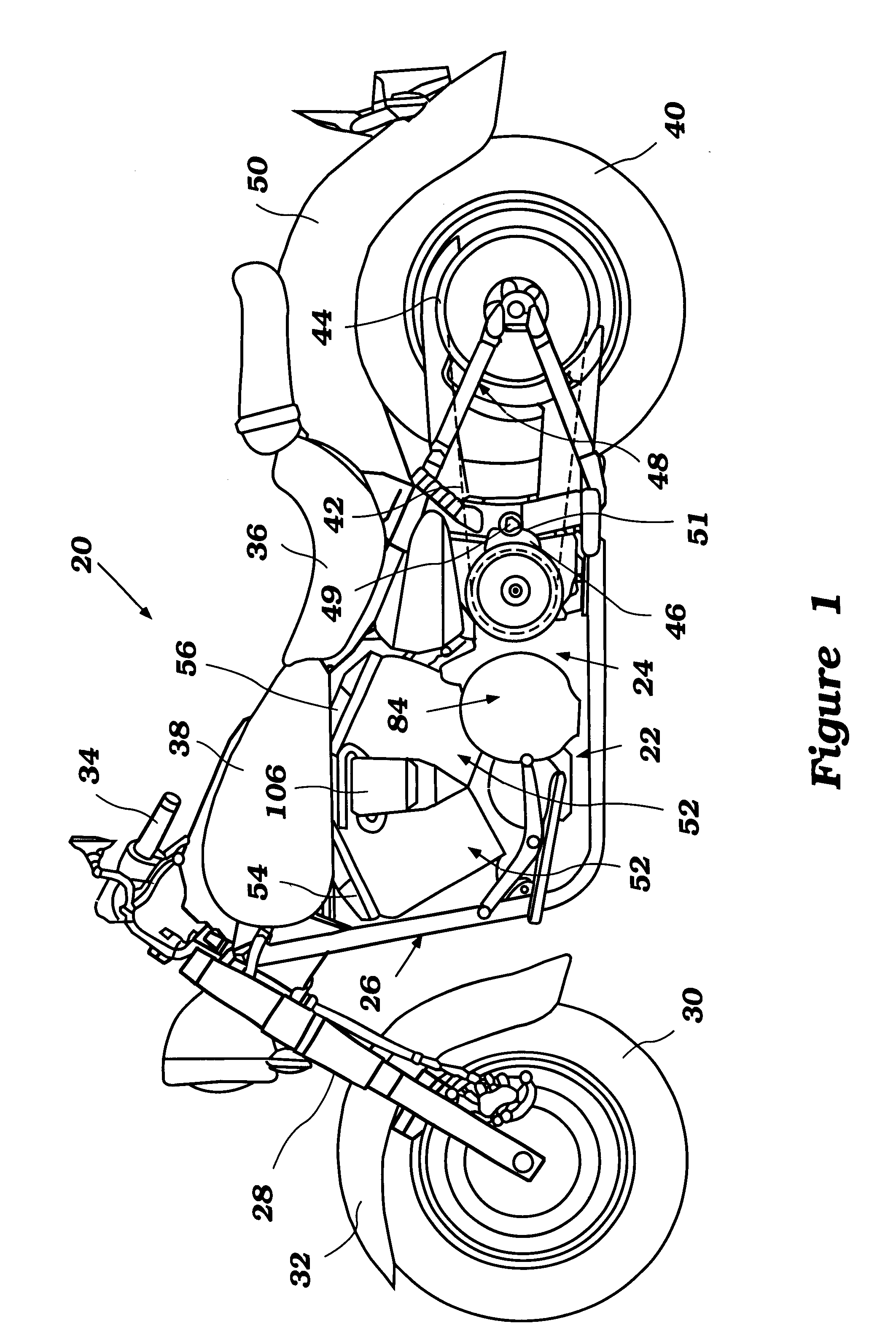
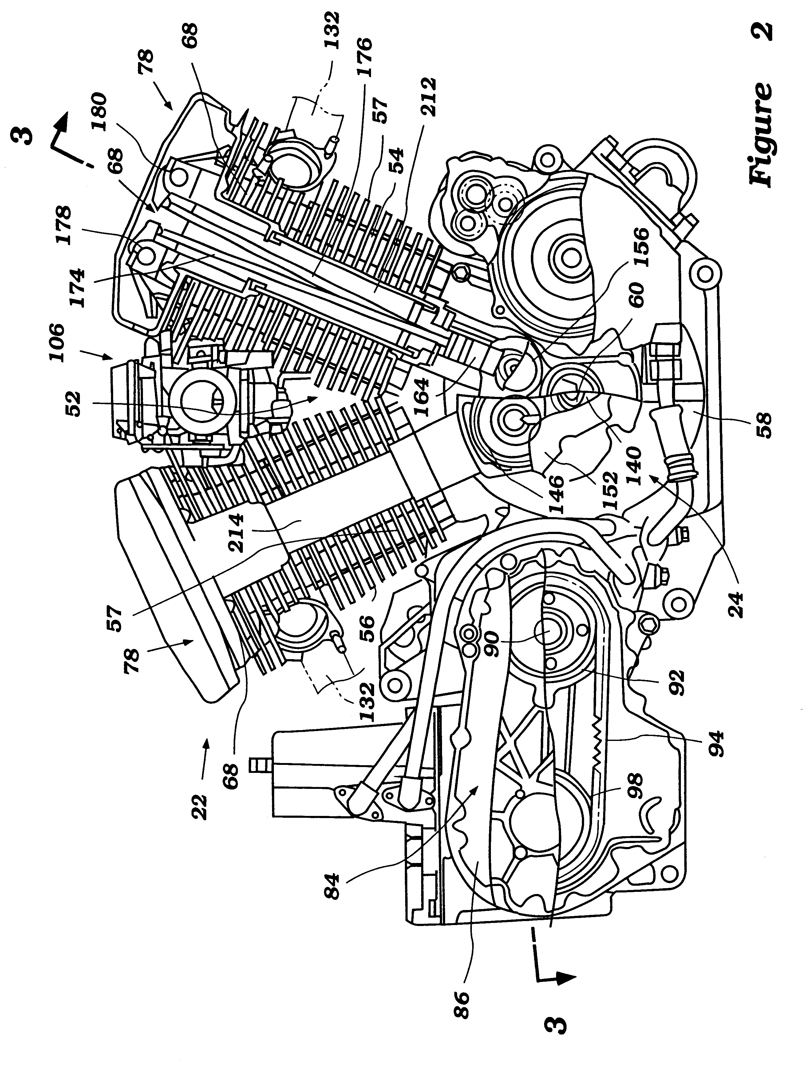
With reference initially to FIG. 1, a motorcycle is illustrated in side elevation view and is identified generally by the reference numeral 20. The motorcycle 20 is powered by an internal combustion engine 22 through a transmission 24 which is constructed in accordance with certain features, aspects and advantages of the present invention. The motorcycle 20 is shown as a typical environment in which the present invention can be used.
As is known to those of ordinary skill in the art, the motorcycle 20 is generally comprised of frame assembly 26 upon which the engine 22 is suspended. This frame assembly 26 also dirigibly supports a front fork 28 to which a front wheel 30 is rotatably journaled. A front fender 32 covers at least a portion of this front wheel 30. The steering of the vehicle is controlled by handlebar assembly 34 that is fixed to the upper end of the illustrated front fork 28 in a manner well known to those of ordinary skill in the art.
A rider seat 36 is carried by the f...
PUM
 Abstract
Description
Claims
Application Information