Motorcycle wheel brake mechanism

Inactive Publication Date: 2002-05-14
MILESI GIORGIO +2
View PDF10 Cites 33 Cited by
  • Summary
  • Abstract
  • Description
  • Claims
  • Application Information

AI Technical Summary

Problems solved by technology

One of the problems of such discs arises precisely from the heating they experience during braking so that, normally, the exterior part has a number of openings through it to facilitate cooling.
However, on cross and trial motorcycl

Method used


Image

  • Motorcycle wheel brake mechanism
  • Motorcycle wheel brake mechanism

Examples


Embodiment Construction

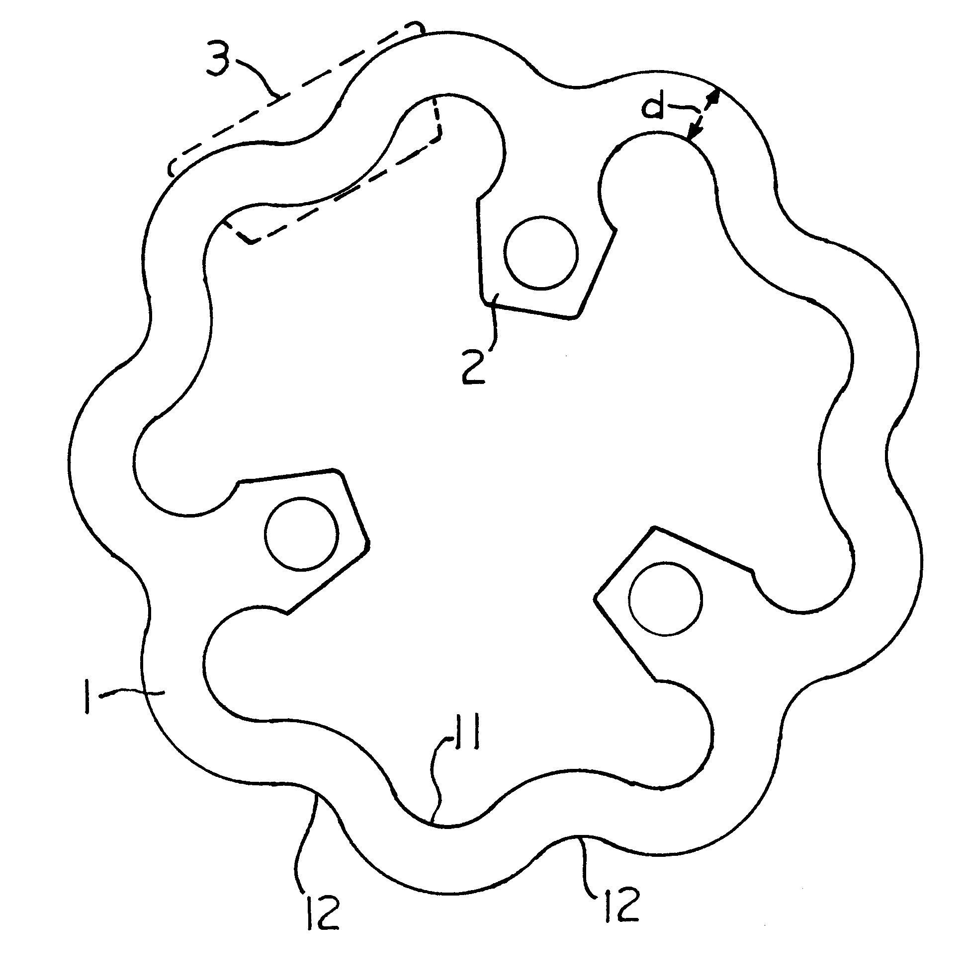
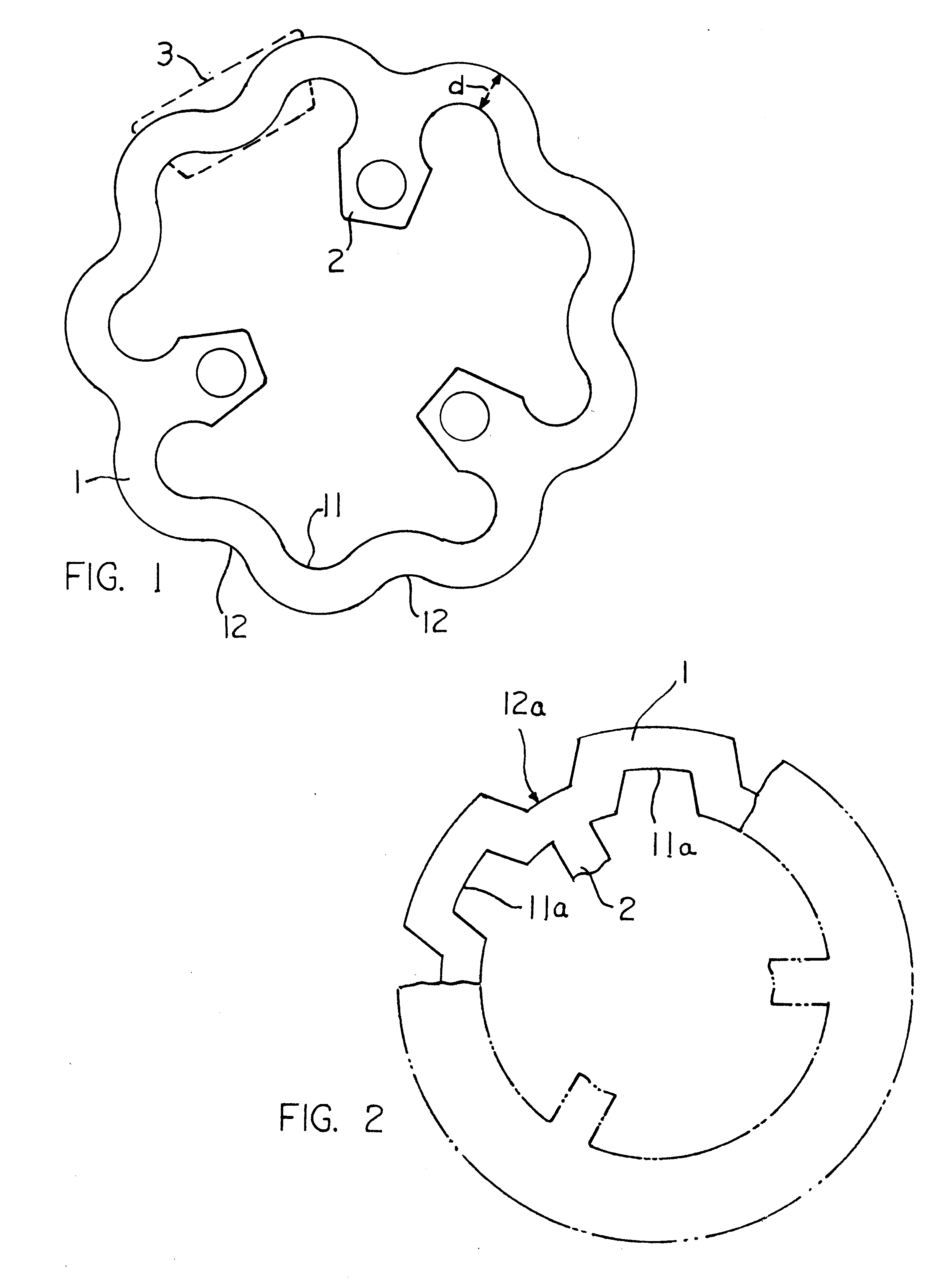
To overcome these problems, particularly on cross and trial motorcycles, the brake disc which is the subject of this invention has been designed with a number of constructional features on the peripheral section forming the brake band. These discs are preferably constructed by laser cutting, made from a high carbon stainless steel mixed material, based on 420 stainless steel materials.

In this invention, said peripheral part of the disc does not have inside holes, so that the problem of the accumulation and retention of mud inside them is overcome; said peripheral section also has a series of off-sets on its inside and outside edges of the same thickness as the rest of the section so as to reduce the total weight of the disc, facilitate its cooling and prevent mud from being retained inside.

Said off-sets on the inside and outside edges of the peripheral section of the disc are preferably arranged alternately so that the width of said section is substantially constant. As a result, du...


PUM


Abstract

A brake disc for a wheel constituted by a peripheral section, forming a brake band with an interior form enabling it to be fitted to its wheel, the brake band forms two lateral flat and parallel surfaces on which a brake shoe can act, said peripheral section having a series of off-sets on its inside and outside edges.

Description

OBJECT OF THE INVENTIONAs its title suggests, this invention refers to a brake disc for motorcycles or the like, with a series of constructional features on the peripheral part forming the brake band.BACKGROUND TO THE INVENTIONMotorcycle brake discs generally have an external section which is ring-shaped, flat, and not very thick, on which the brake shoes operate; this external section forms the brake band. Said discs also have an interior form designed to allow them to be fixed on to the wheel. This interior form and the exterior section may be a monobloc unit or may be joined in such as way as to permit expansion of the outer section so that it will not become deformed when it heats.One of the problems of such discs arises precisely from the heating they experience during braking so that, normally, the exterior part has a number of openings through it to facilitate cooling.On so-called road motorcycles, the discs reach very high temperatures because of the speeds involved, so that...

Claims


Application Information

Patent Timeline
IPC IPC(8): F16D65/12
CPCF16D65/12F16D2065/1392F16D2065/1308F16D2065/026
Inventor MILESI, GIORGIOMILESI, UMBERTOMILESI, ALFREDO
Owner MILESI GIORGIO
Why Eureka
Try Eureka