Bicycle lock holder

a technology for bicycle locks and holder plates, which is applied in the field of holder plates, can solve the problems of moving parts that can jam, lock is securely and unobtrusively stowed, and the prior art holders have not completely met these objectives

Inactive Publication Date: 2002-07-23
SCHLAGE LOCK
View PDF5 Cites 50 Cited by
  • Summary
  • Abstract
  • Description
  • Claims
  • Application Information

AI Technical Summary

Problems solved by technology

Prior art holders have not completely met these objectives.
While these prior art brackets achieve their intended function, each has its drawbacks.
Such drawbacks include (1) a loose fit so that the lock rattles when riding the bicycle (2) only one viable bicycle mounting position because there is only one way that the U-lock can be attached to the bracket, (3) a safety issue wherein the U-lock can be ejected from the bracket during an accident causing injury, and (4) moving parts that can jam if they become dirty.
With such simultaneous engagement, the lock is securely and unobtrusively stowed on the bicycle frame.

Method used


Image

  • Bicycle lock holder
  • Bicycle lock holder
  • Bicycle lock holder

Examples


Embodiment Construction

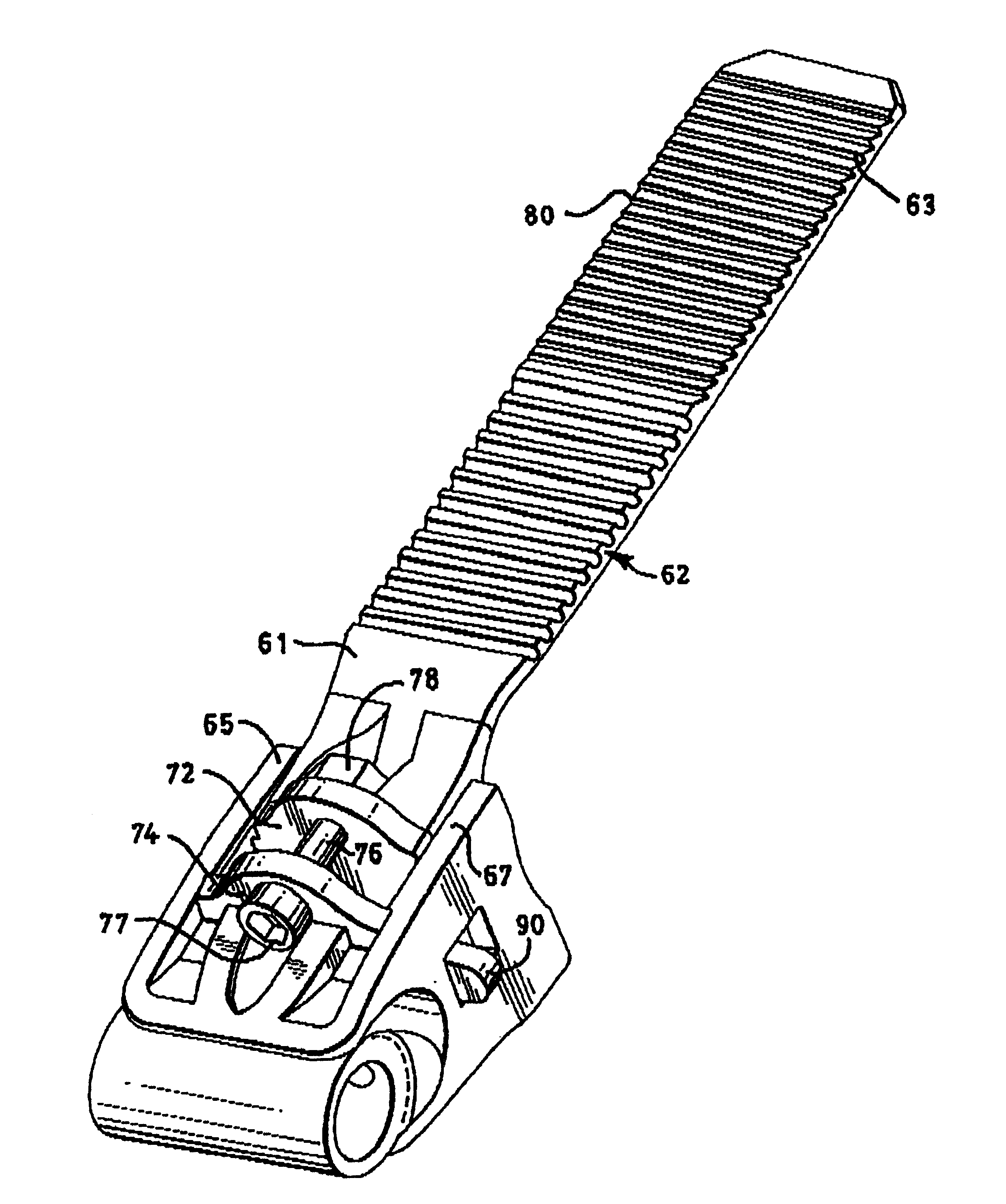
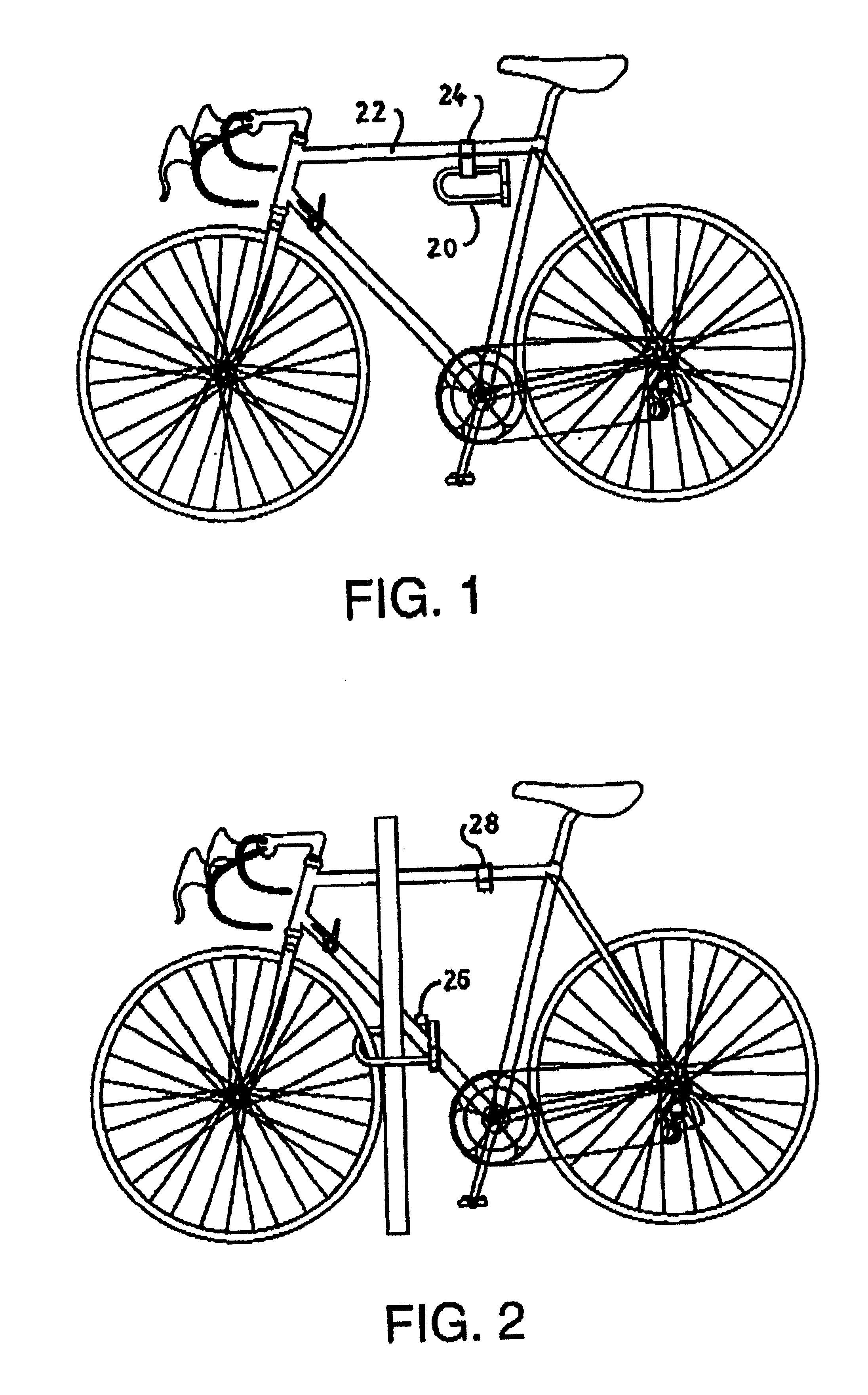
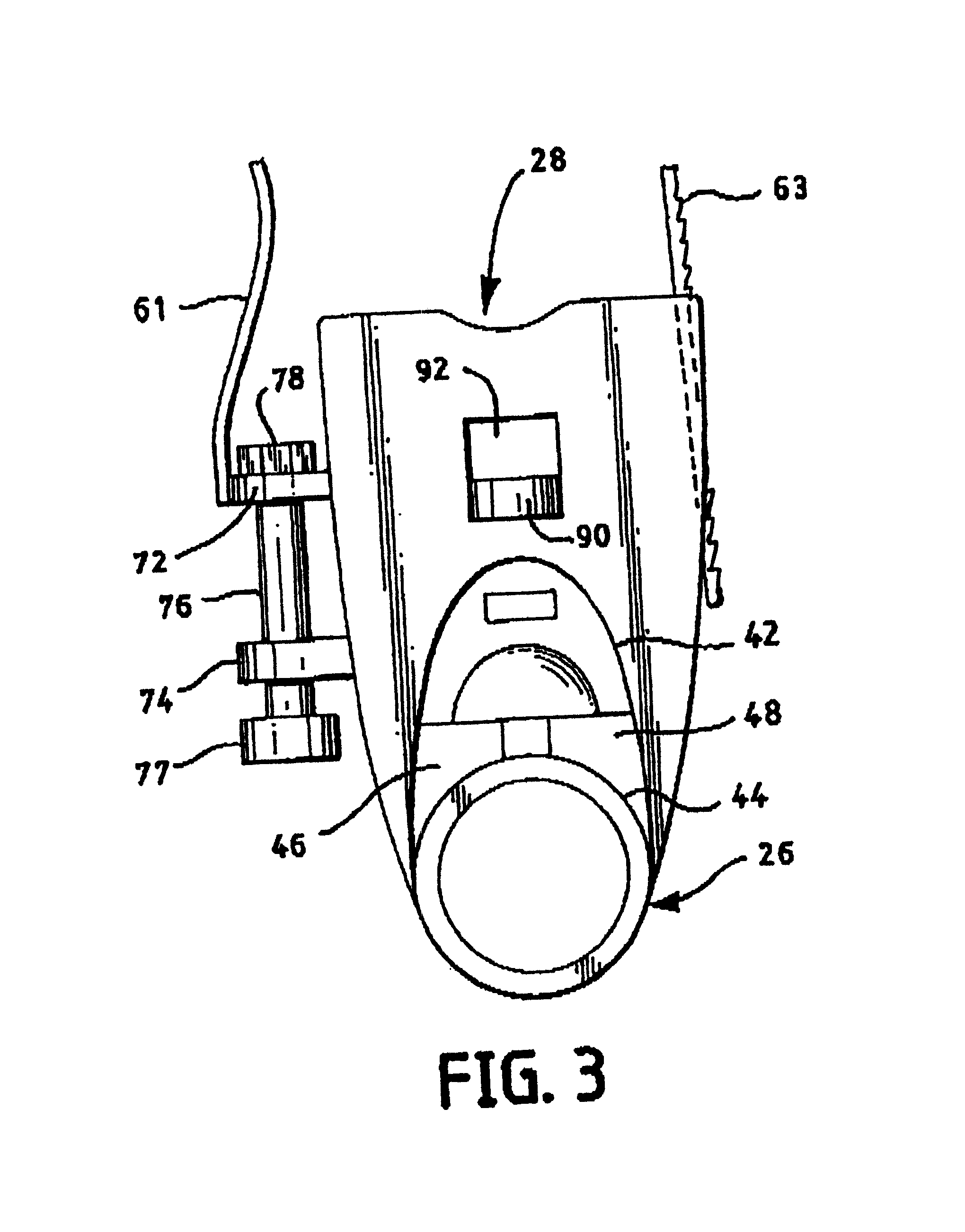
FIGS. 1 and 2 show a U-lock 20 held on a strut 22 of a bicycle frame by a holder 24, which comprises a brace 26 and a bracket 28. Brace 26 is securely connected to a leg of U-lock 20. Bracket 28 is securely connected to a strut 22 of the bicycle frame. The brace and the bracket are particularly designed for easy engagement with each other, and for easy disengagement from each other. With engagement, U-lock 20 may be securely and unobtrusively stowed on the bicycle frame as shown in FIG. 1. With disengagement, the U-lock is readily available for tying the bicycle to a secure post or other station as shown in FIG. 2.

The brace includes, as paraxially distributed components: a collar portion 30, a tongue portion 32, and intermediate articulated portions 34, 36 between the collar portion and the tongue portion. Collar portion 30 is adapted to receive a leg of U-lock 20. Collar portion 30 is adapted to be tightly fixed to this leg by a threaded bore and set screw arrangement 38. Tongue po...


PUM


Abstract

A U-lock holder for stowing a U-lock on a bicycle frame. The holder comprises a brace for connection to a leg of the U-lock, and a bracket for connection to a part of the bicycle frame. The brace and the bracket are adapted for engagement and disengagement with and from each other. The brace includes a collar, a tongue, and opposed intermediate articulations between the collar and the tongue. The bracket includes a mount, a channel, a saddle, and opposed intermediate guides between the channel and the saddle. The collar is adapted to receive and to be affixed to a leg of the U-lock. The mount is adapted to abut against the bicycle frame. A strap tightly affixes the bracket to the bicycle frame. Mating of the brace and the bracket effect simultaneous engagement of (1) the tongue and the articulations of the brace, and (2) the channel and the guides of the bracket.

Description

1. Field of the InventionThe present invention relates to holders for temporarily stowing bicycle locks, e.g. U-locks and cable locks, when not in use, and for releasing the locks for ready use when needed. Such U-locks arc of the type having a shackle and a crossbar as mating parts. Such cable locks are of the type having a cable and an end bar as mating parts. The mating parts are adapted to tie the frame of a parked bicycle to a secure post or other station.2. The Prior ArtSince the invention of bicycle U-locks and cable locks, a variety of holders have been proposed for removably carrying such a lock when the bicycle is in use, rather than parked. Such a U-lock typically comprises a semi-enclosure member or shackle having legs or fittings with configured feet, a straight crossbar having openings for reception of these feet, and a locking mechanism in the crossbar for retaining or releasing these feet. Such a cable lock typically comprises a cable having at one end a leg or fitti...

Claims


Application Information

Patent Timeline
Patent Type & Authority Patents(United States)
IPC IPC(8): B62J11/00B62H5/00
CPCB62H5/00B62J11/00B62H2005/008E05B2067/386Y10S224/935Y10T70/483Y10T70/5872
Inventor MCDAID, CORNELIUSFIEGENER, JOHN D.ZURASKI, ROBERT D.
Owner SCHLAGE LOCK
Why Eureka
Try Eureka