Cabinet frame

a cabinet and frame technology, applied in the field of cabinetry, can solve the problems of not being protected against damage, sealing strips cannot be supported along the external side, and not being able to achieve perfect sealing

Inactive Publication Date: 2002-08-06
RASMUSSEN KNUD
View PDF13 Cites 62 Cited by
  • Summary
  • Abstract
  • Description
  • Claims
  • Application Information

AI Technical Summary

Benefits of technology

The invention will in the following be explained more detailed, with reference to the accompanying drawings.

Problems solved by technology

Thus, the sealing strips will be visible on the external side, and they will not be protected against damage.
Moreover, the sealing strips will not be supported along the external side at the corners, and they may be positioned such that a perfect sealing is not achieved.

Method used


Image

  • Cabinet frame
  • Cabinet frame
  • Cabinet frame

Examples


Embodiment Construction

OF EMBODIMENTS

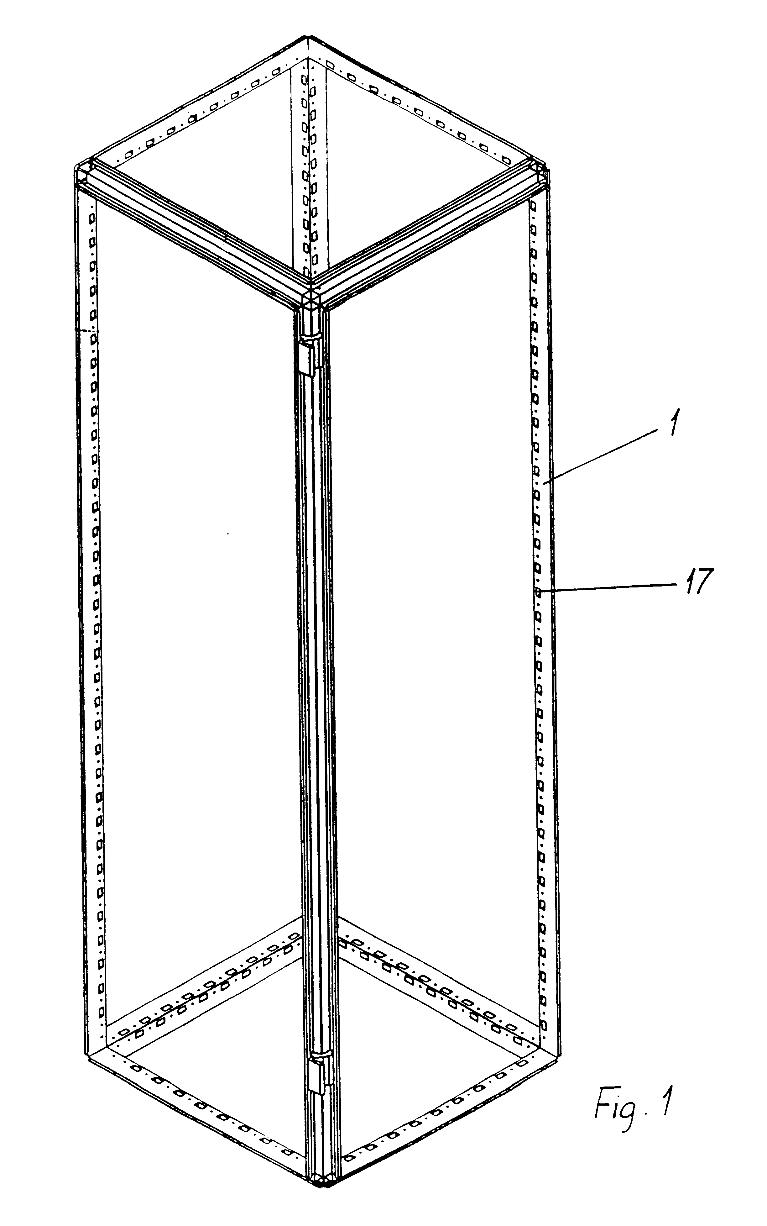
FIG. 1 shows a framework for a cabinet in accordance with the invention, with twelve profiles 1 connected together in corners by use of corner members, possibly also by welding. Holes 17 are formed in the profiles 1, for instance for mounting of equipment internally in the cabinet.

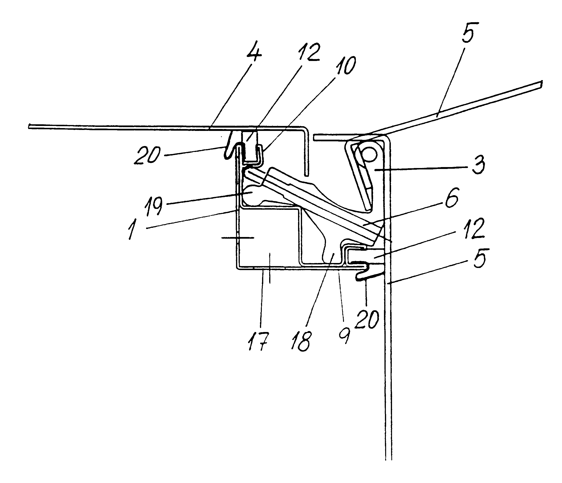
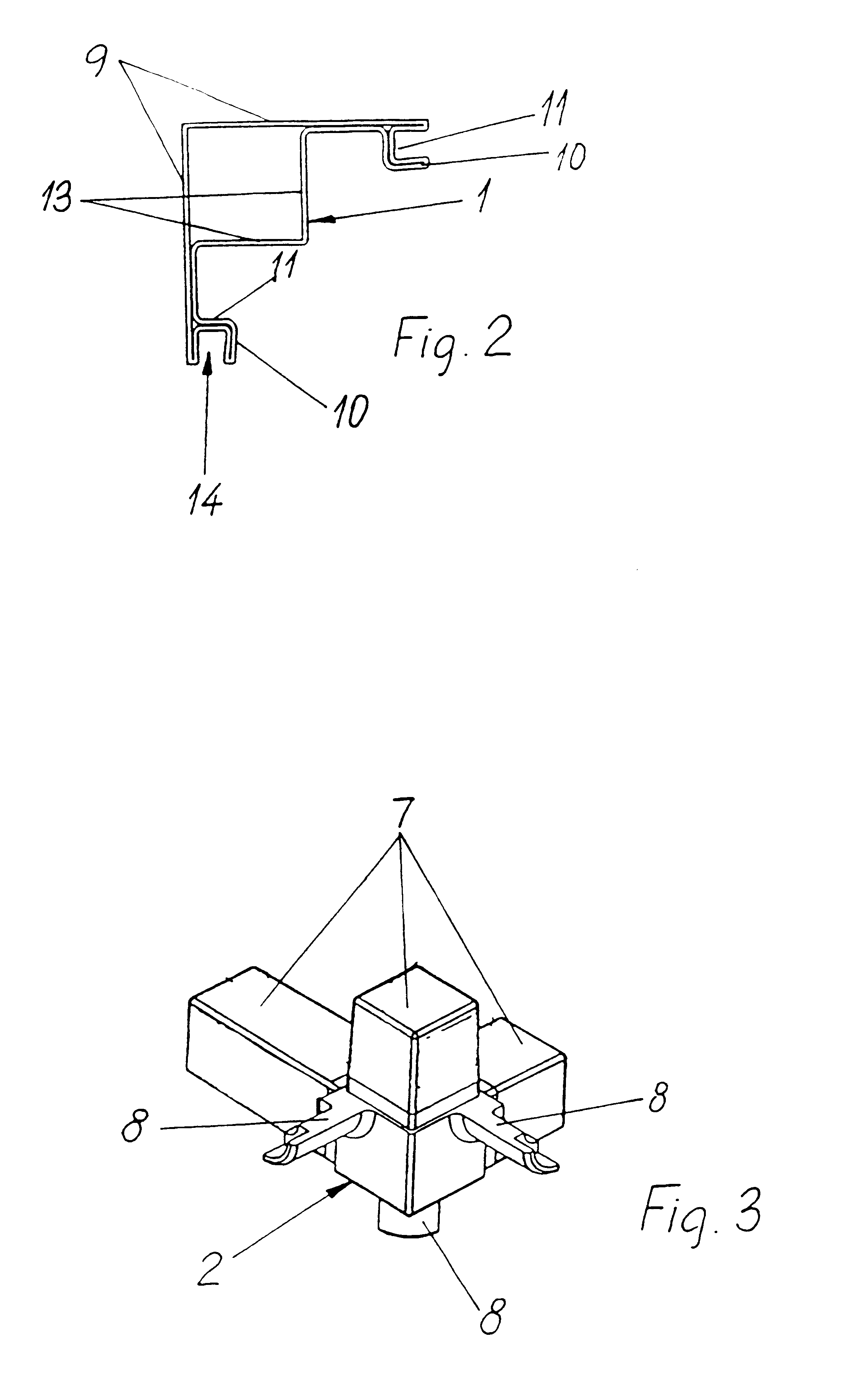
FIG. 2 shows a possible cross sectional shape for a profile 1 used in the cabinet. The profile comprises two external walls 9, two internal walls 13 which together with portions of the external walls 9 delimit a chamber with an approximately square cross section, and grooves 14 for sealing strips, delimited by portions of the walls 9, and bottoms 11 and side walls 10. The shown profile is made by profiled rolling of a sheet from a blank being rolled to a closed profile and being welded together to form a tube, for instance of steel, but it will be understood that the profile can be formed by folding and by extrusion, for instance of light metal. By extrusion the walls will of course be compac...


PUM


Abstract

A cabinet having at least one door (5), in particular an electrical cabinet, comprising a framework made up of right angled metal profiles (1) which are mutually connected by use of corner members (2) having fastening elements (7) inserted in cavities in the profiles, whereby each profile is symmetrical about a plane in 45° relatively to two of the main directions of the cabinet and comprises two grooves (14) situated symmetrically about said plane, for sealing strips (12), said grooves (14) being directed outwardly from the interior of the cabinet, whereby the sealing strips (12) are in engagement with external wall panels, and whereby the bottom (11) of each groove (14) is situated inwardly of a respective profile wall (9) which delimits the profile towards the interior of the cabinet. The grooves (14) are situated along a respective free edge on the profile, whereby the profile is open from the external side, and the bottom (11) and/or the inner side wall (10) of each groove forms an abutment for fastening of hinge pans (3) at least in one of the profiles.

Description

The present invention relates to a cabinet, and in particular an electrical cabinet, i.e. a cabinet adapted to contain electrical installations, in particular for use in places where there is a danger of seeping in of water into the cabinet, and in places where electrical or magnetical noise occurs. The cabinet is made up by a framework which form the edges of a parallelepiped, i.e. that the framework consists of twelve profiles, and the framework is closed by wall panels and at least one door.In places where for instance water is flushed there is a need for watertight electrical cabinets, among else for preventing that the water causes short-circuiting and damages on electrical installations in the cabinet. There is also a need for sealing when components in the cabinet are to be protected against electrical or magnetical noise or when the surroundings are to be protected against such influence from components in the cabinet.An example of such a cabinet is known from DE C1 3344598....

Claims


Application Information

Patent Timeline
Patent Type & Authority Patents(United States)
IPC IPC(8): A47B47/00A47B47/03E05D5/02E05D5/00H02B1/30H02B1/00H02B1/01
CPCA47B47/0008A47B47/03E05D5/0238H02B1/301H02B1/013H02B1/014E05Y2900/208
Inventor RASMUSSEN, KNUD
Owner RASMUSSEN KNUD
Why Eureka
Try Eureka