High pressure fuel injection pipe for diesel engine

a high-pressure fuel injection and diesel engine technology, which is applied in the direction of hose connections, pipe couplings, couplings, etc., can solve the problems of increasing the toxic substances in the exhaust gas, affecting the quality of the oil, and affecting the performance of the engin

Inactive Publication Date: 2002-08-13
USUI KOKUSAI SANGYO KAISHA LTD
View PDF5 Cites 60 Cited by
  • Summary
  • Abstract
  • Description
  • Claims
  • Application Information

AI Technical Summary

Benefits of technology

In the high pressure fuel injection pipe for a diesel engine according to the present invention, the annular washer having the radially extending groove or small hole is used as the press member interposed between the connecting head of the injection pipe body and the fastening nut, or the through hole is formed in the fastening nut per se, and the seal member is preferably disposed in the vicinity of the outer end portion of the threaded engagement portion defined between the fastening nut and the nozzle holder. Accordingly, the leakage of the fuel leaked from the seat face defined between the press seat portion of the connecting head of the injection pipe body and the pressure receiving seat portion of the nozzle holder into the inside of the head cover can be prevented and simultaneously the leaked fuel can be led to the outside of the head cover so that the leakage of the fuel caused by the abnormal condition of the seat face, the shortage of the fastening torque of the fastening nut or the failure to fasten the fastening bolt can be instantly detected in a trial operation after assembling an engine whereby the countermeasure against the leakage of the fuel can be taken promptly.

Problems solved by technology

Accordingly, there have been problems that an engine oil is diluted (dilution) thus degrading the quality of the oil and simultaneously the oil level is elevated thus producing a white fume in an exhaust gas and increasing toxic substances in the exhaust gas.

Method used


Image

  • High pressure fuel injection pipe for diesel engine
  • High pressure fuel injection pipe for diesel engine
  • High pressure fuel injection pipe for diesel engine

Examples


first embodiment

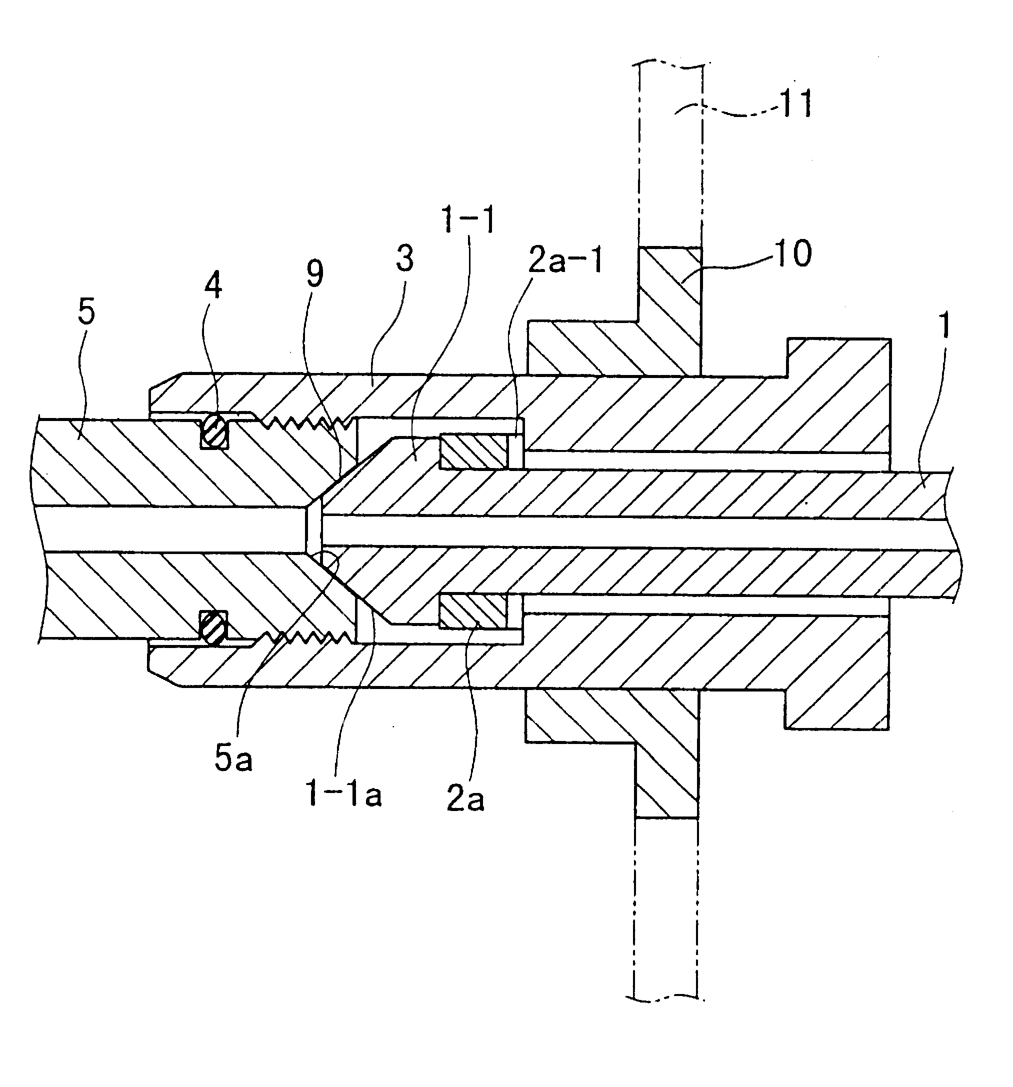
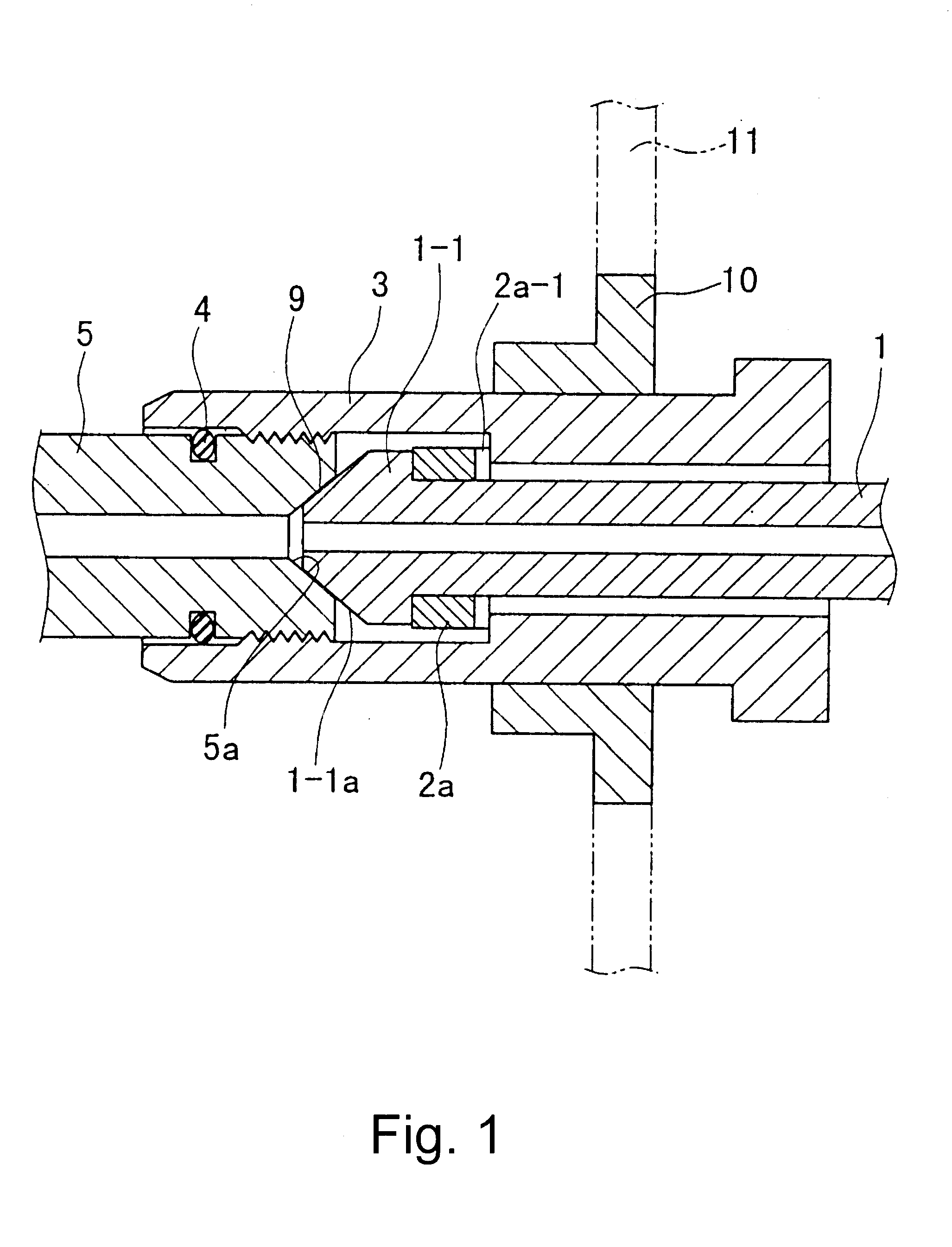
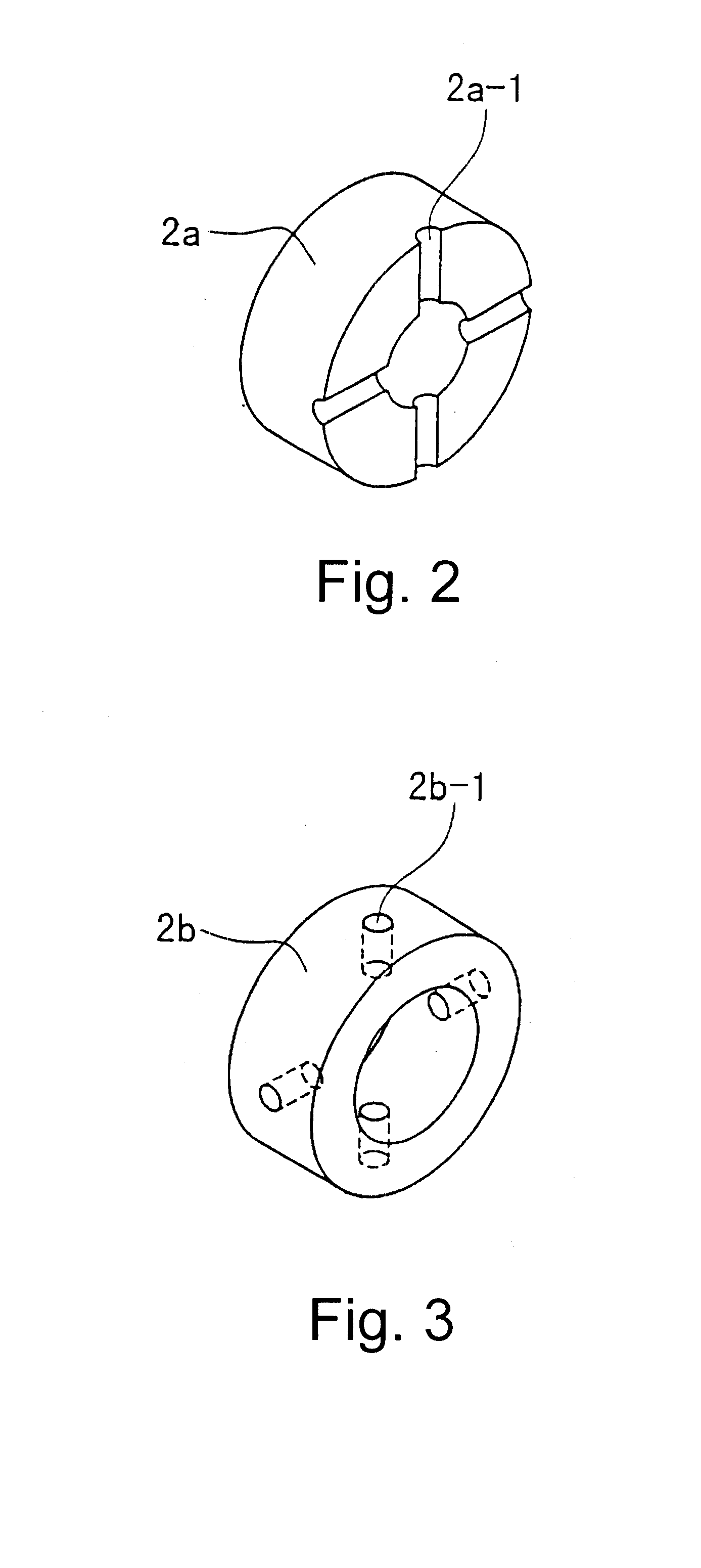
Further, in the high pressure fuel injection pipe for a diesel engine of the first embodiment shown in FIG. 1, the fastening nut 3 having the hole bolt shape is assembled to the injection pipe body 1 such that the annular washer 2a is disposed behind the connecting head 1-1 formed on the end portion of the injection pipe body 1 with the grooves 2a-1 having the arcuate cross-sectional shape disposed at the side of the annular washer 2a opposite to the side of the annular washer 2a which comes into contact with the connecting head 1-1. Then, the press seat portion 1-1a formed on the connecting head 1-1 of the injection pipe body 1 is brought into contact with and is engaged with a pressure receiving seat portion 5a of the nozzle holder 5 to form the seat portion 9. Along with the pressing of the connecting head 1-1 generated by the threaded engagement of the fastening nut 3 to the nozzle holder 5, the injection pipe body 1 is connected to the nozzle holder 5 by fastening. The O-ring 4...

second embodiment

Subsequently, in the high pressure fuel injection pipe for a diesel engine of the second embodiment shown in FIG. 4, as means for leading the fuel leaked from the seat portion 9 to the outside of the head cover 11, the through hole 7-1 is formed between an inner peripheral surface of the fastening nut 3 in the vicinity of the connecting head 1-1 of the injection pipe body 1 and the outer end portion of the fastening nut 3. Due to such a constitution, the fuel leaked from the seat portion 9 is led to the outside of the head cover 11 through this through hole 7-1. In this case, and annular washer 2c may not be provided with an arc-shaped groove or a thin hole 2b-1.

Further, in the high pressure fuel injection pipes for a diesel engine of the third and fourth embodiments shown in FIG. 5 and FIG. 6, as means for leading the fuel leaked from the seat portion 9 to the outside of the head cover 11, the through holes 7-2, 7-3 are respectively formed between the inner peripheral surface of th...

fifth embodiment

Further, in the high pressure fuel injection pipe for a diesel engine of the fifth embodiment shown in FIG. 7, as means for leading the fuel leaked from the seat portion 9 to the outside of the head cover 11, the through hole 7-4 is formed between the inner peripheral surface of the fastening nut 3 in the vicinity of the connecting head 1-1 of the injection pipe body 1 and a gap defined between the fastening nut 3 at the back surface side of the annular washer 2c and the injection pipe body 1. Due to such a constitution, the fuel leaked from the seat portion 9 is led to the outside of the head cover 11 through this through hole 7-4 and a gap defined between the fastening nut 3 and the injection pipe body 1.


PUM


Abstract

The invention is to provide a high pressure fuel injection pipe for a diesel engine wherein a fuel, leaked from a seat port is discharged to the outside of a head cover without leaking into the head cover so that a leakage of fuel can be promptly detected and is directed to the high pressure fuel injection pipe formed by abutting and engaging a pressure portion formed on a connecting head of a fuel injection pipe body to a pressure receiving seat portion of a counterpart member so as to provide a firm connection of the fuel injection pipe body to the counterpart member by screwing a fastening nut to press the connecting head to the counterpart member, wherein an annular washer having at least one groove or through hole formed in a radial direction on the circumference of the washer and a seal member is disposed in the vicinity of an outer end portion of a threaded engagement potion defined between the fastening nut and the counterpart member so that a fuel leaked into the inside of the fastening nut from a seat portion defined between the pressure seat portion formed on the connecting head and the pressure receiving seat of the counterpart member may be discharged to the outside through the groove or through hole. Alternatively, the leaked fuel may be discharged to the outside through a through hole which is formed on the fastening nut.

Description

1. Field of the InventionThe present invention relates to a high pressure fuel injection pipe for a diesel engine having a small tubular diameter of approximately not more than 30 mm which is arranged in the vicinity of a diesel engine as a fuel supply passage specially in the field of a diesel engine, and more particularly to a high pressure fuel injection pipe for a diesel engine which is characterized by its connection structure with a counterpart member such as a nozzle holder.2. Related Art StatementAs shown in FIG. 10 as an example, a nozzle holder side of a high pressure fuel injection pipe for a diesel engine is constituted such that an injection pipe body 21 is provided with a connecting head 21-1 at an end portion thereof and a fastening nut (generally called "hole bolt") 23 is assembled to the injection pipe body 21 by way of a press member 22 such as a washer which is disposed behind the connecting head 21-1, and a press seat portion 21-Ia formed on the connecting head 2...

Claims


Application Information

Patent Timeline
Patent Type & Authority Patents(United States)
IPC IPC(8): F02M55/00F16L19/02F02M55/02
CPCF02M55/002F02M55/005F16L19/02F16L2201/30
Inventor KATO, NOBUO
Owner USUI KOKUSAI SANGYO KAISHA LTD
Why Eureka
Try Eureka