Artificial respiration apparatus
a technology of respiration apparatus and artificial heart, which is applied in respiratory apparatus, life-saving devices, fire rescue, etc., can solve the problems of difficult to obtain a target pressure and control pressur
- Summary
- Abstract
- Description
- Claims
- Application Information
AI Technical Summary
Problems solved by technology
Method used
Image
Examples
embodiment 2
[Embodiment 2]
Description will now be directed to a second embodiment of the present invention with reference to FIG. 16 and FIG. 17.
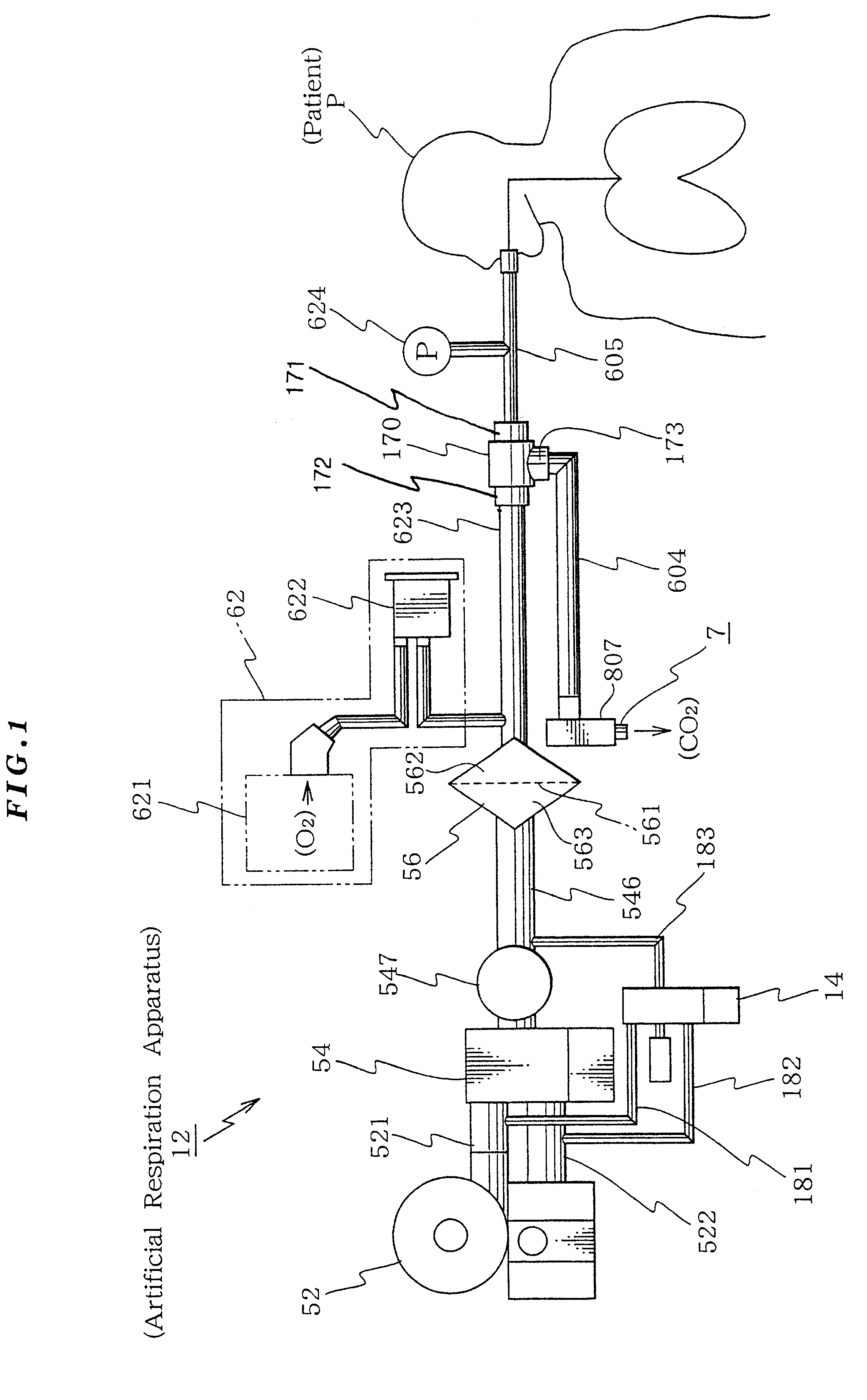
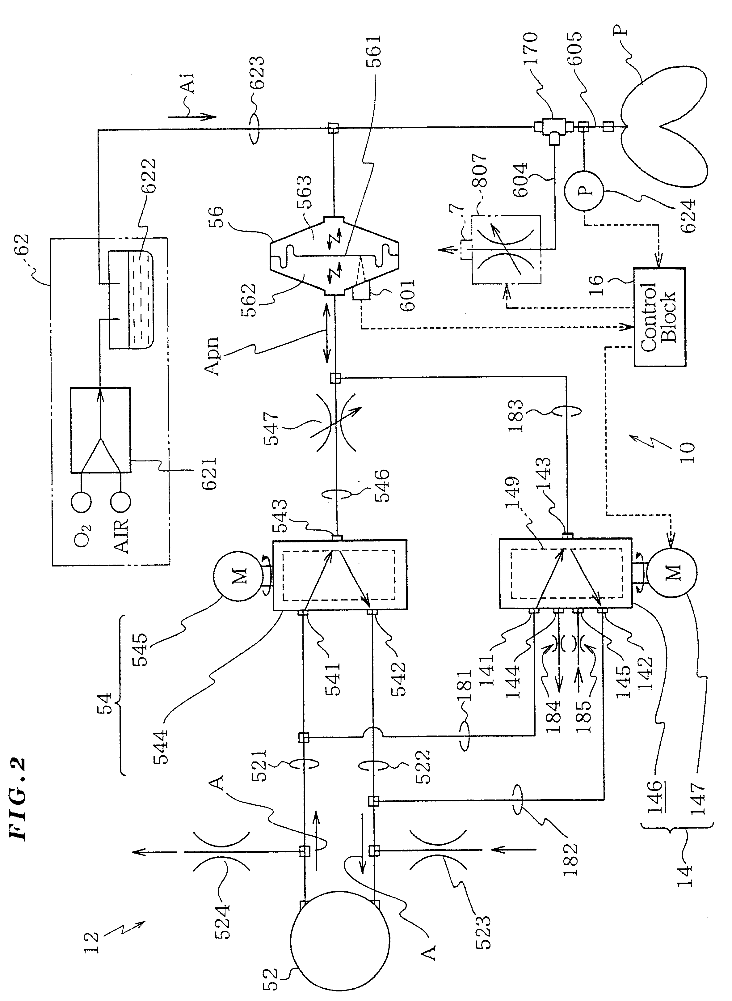
The artificial respiration apparatus 12C according to the second embodiment is identical to the artificial respiration apparatus 12 of the first embodiment except for that switching means 7C is provided instead of the one-way valve and the discharge valve 807.
The switching means 7C is constituted by a cover member 71C and a crank mechanism. The cover member 71C is located at the discharge end 604a of the discharge pipe 604. The cover member reciprocally moves so as to open and close the discharge end 604a. This cover member 71C is mounted inside a cylindrical body 72C arranged on the same axis as the discharge pipe 604 in such a manner that the cover member 71C can reciprocally move inside the cylindrical body 72C. The cover member has a circular shape having an outer diameter greater than the diameter of the discharge end 604a of the discharge pipe 60...
embodiment 3
[Embodiment 3]
Description will now be directed to a third embodiment of the present invention with reference to FIG. 18 and FIG. 19.
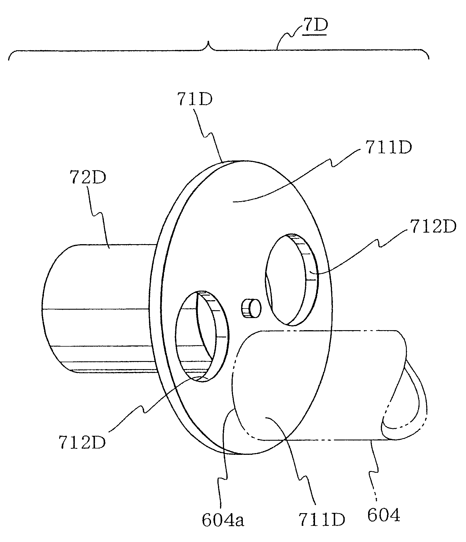
The artificial respiration apparatus 12D is identical to the artificial respiration apparatus 12 except for that a discharge route open / close switching means 7D is provided instead of the one-way valve and the discharge valve 807.
The open / close switching means 7D includes a rotary plate 71D and a drive motor 72D. The rotary plate 71D has through holes 712D and a solid region 711D for closing the discharge end 604a of the discharge pipe 604. This rotary plate 71D is formed as a disc shaped and has its center fixed to the rotary axis of the drive motor 72D. This rotary plate 71D is arranged so that the discharge end 604a of the discharge pipe 604 is closed by the solid region.
The rotary plate 71D has an outer diameter greater than the outer diameter of the discharge end by two or more. Two through holes 721D are formed in this rotary plate, at symmetrical...
embodiment 4
[Embodiment 4]
Description will now be directed to a fourth embodiment of the present invention with reference to FIG. 20 and FIG. 21.
The artificial respiration apparatus 12E according to the fourth embodiment uses another type of open / close switching means 7E instead of the one-way valve as a discharge direction regulating mechanism. This artificial respiration apparatus 12E has a configuration identical to the configuration of the artificial respiration apparatus 12 unless otherwise specified.
The open / close switching means 7E includes: a rotary cylindrical body having a cutoff portion 712E for discharge and a solid portion 711E for closing; a cylindrical frame 72E for rotatably containing this rotary cylindrical body; and a drive motor 73E for rotating the rotary cylindrical body 71E.
The cylindrical frame 72E is arranged at the discharge end of the discharge pipe 604 (see the alternate long and two short dashes line in FIG. 21). This cylindrical frame has an open top and a solid bo...
PUM
 Abstract
Description
Claims
Application Information
 - R&D
- Intellectual Property
- Life Sciences
- Materials
- Tech Scout
- Unparalleled Data Quality
- Higher Quality Content
- 60% Fewer Hallucinations
Browse by: Latest US Patents, China's latest patents, Technical Efficacy Thesaurus, Application Domain, Technology Topic, Popular Technical Reports.
© 2025 PatSnap. All rights reserved.Legal|Privacy policy|Modern Slavery Act Transparency Statement|Sitemap|About US| Contact US: help@patsnap.com


