

Head for checking linear dimensions of parts
a technology for parts and heads, applied in the direction of mechanical measuring arrangements, instruments, measurement devices, etc., can solve the problems of poor ruggedness of features and the over-constraint of the constraint system used in these heads
- Summary
- Abstract
- Description
- Claims
- Application Information
AI Technical Summary
Problems solved by technology
Method used
Image

Examples
Embodiment Construction
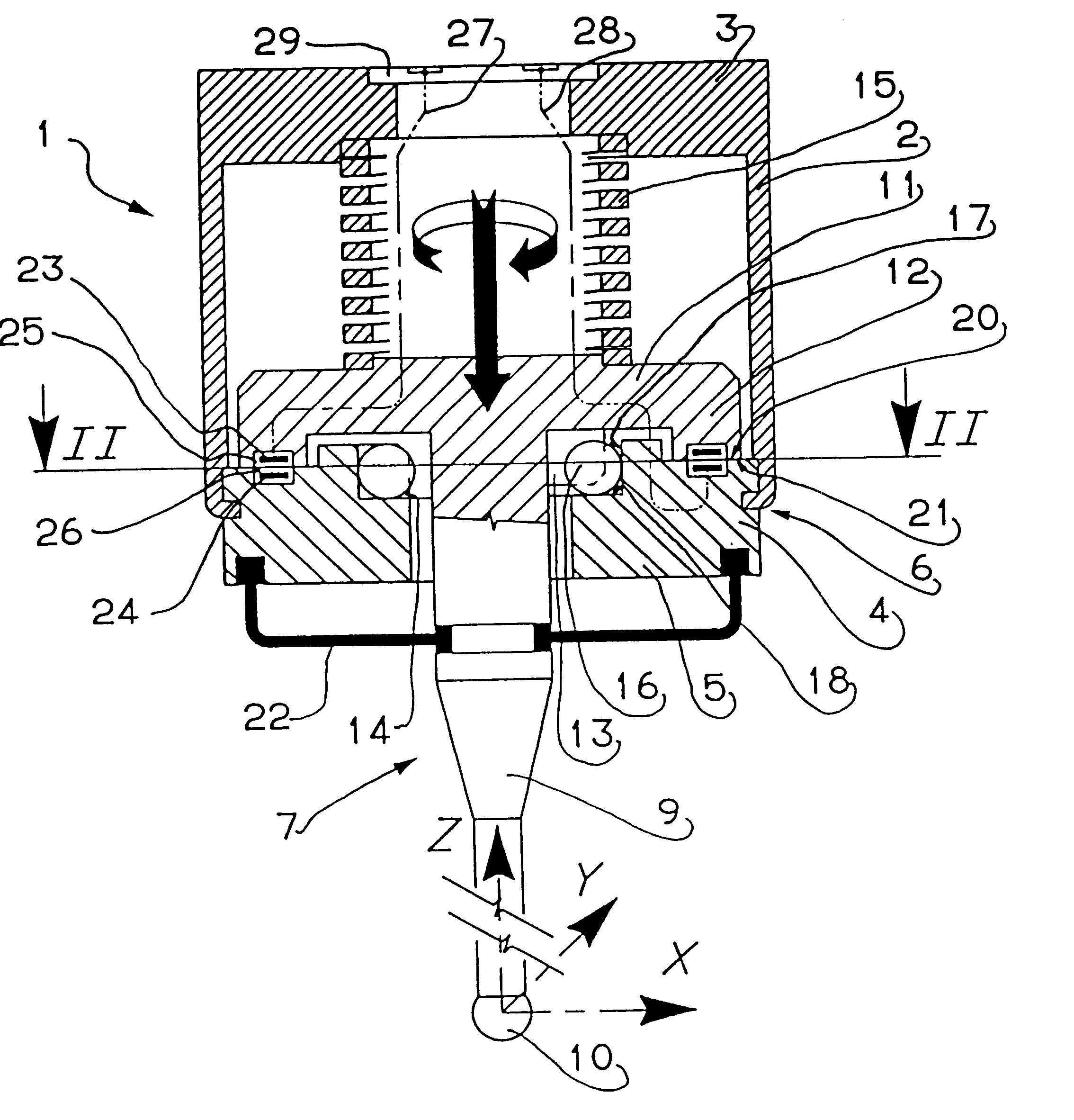
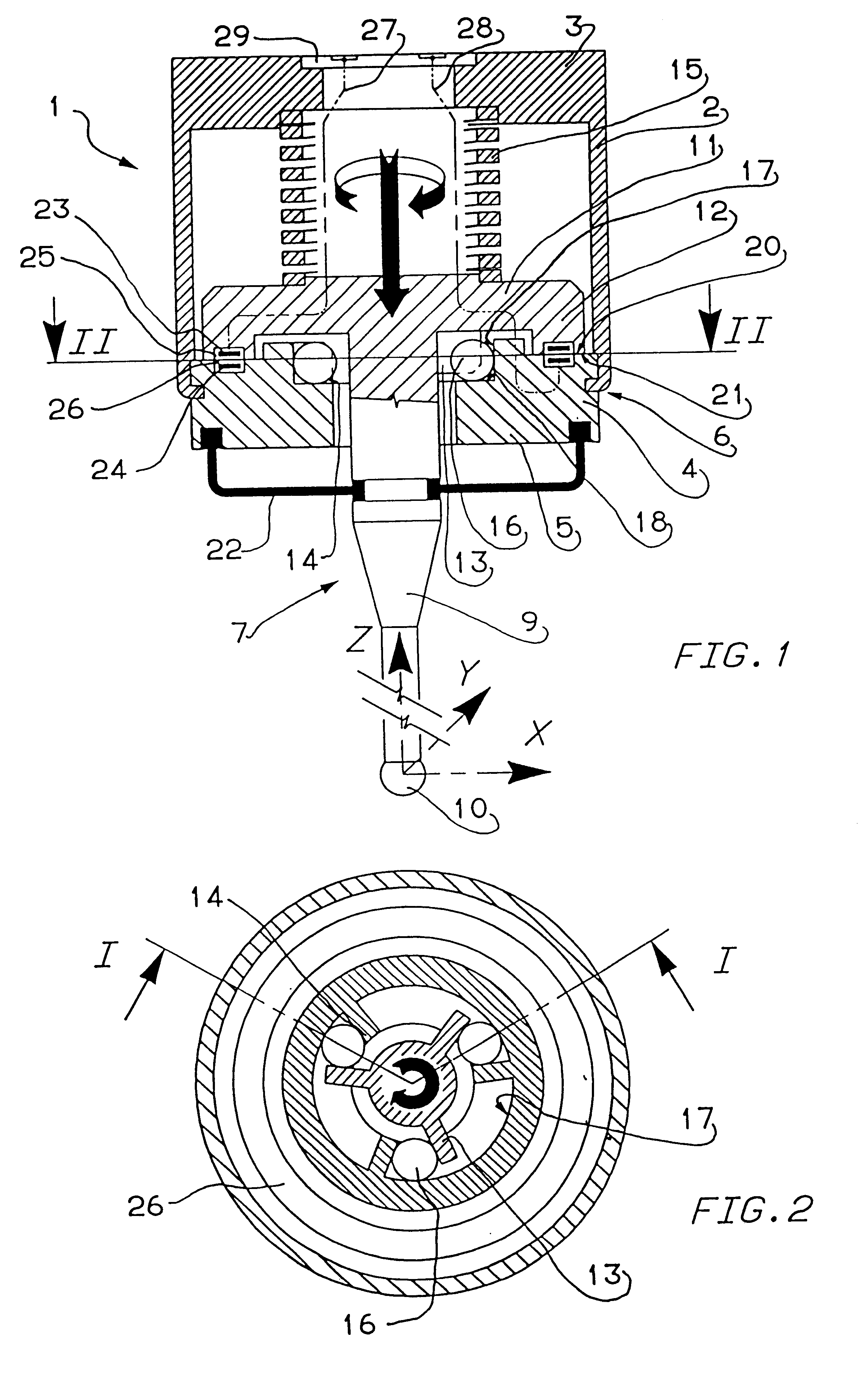
The head of FIGS. 1 and 2 comprises a support structure, or casing 1 including a first member 2, substantially cylindrical and having an upper base 3, and a second member 4, substantially annular, with a lower base 5. The first and the second member 2, 4 are secured to each other, in correspondence with the ends opposite to the bases 3 and 5, by a fixed or detachable coupling 6 represented in a very schematic way.
The movable arm-set 7 of the head comprises an arm 9 carrying at an end external to casing 1 a feeler 10 and at the other end a member having the shape of a circular disc 11, with an annular portion 12 protruding towards feeler 10.
Three plates or vanes 13 with plane walls are fixed to the arm-set 7, between the lower surface of disc 11 and the upper portion of arm 9. The walls of plates 13 lie in radial directions and along the longitudinal geometric axis Z of the head and are angularly spaced apart, with respect to the Z axis, at 120.degree. from one another.
Three other pl...
PUM
 Abstract
Description
Claims
Application Information