
Sealing device for a bearing

a sealing device and bearing technology, applied in the direction of mechanical equipment, machines/engines, transportation and packaging, etc., can solve the problems of premature reduction of sealing performan

Inactive Publication Date: 2002-11-19
NTN CORP
View PDF9 Cites 46 Cited by
  • Summary
  • Abstract
  • Description
  • Claims
  • Application Information

AI Technical Summary

Problems solved by technology

This is problematic in that once the outer peripheral surface of the inboard end of the inboard inner race 36 rusts, debris of rust detaching from such outer peripheral surface will accelerate wear of the bifurcated radial lips 38b and 38c, resulting in premature reduction in sealing performance.

Method used


Image

  • Sealing device for a bearing
  • Sealing device for a bearing
  • Sealing device for a bearing

Examples


first embodiment

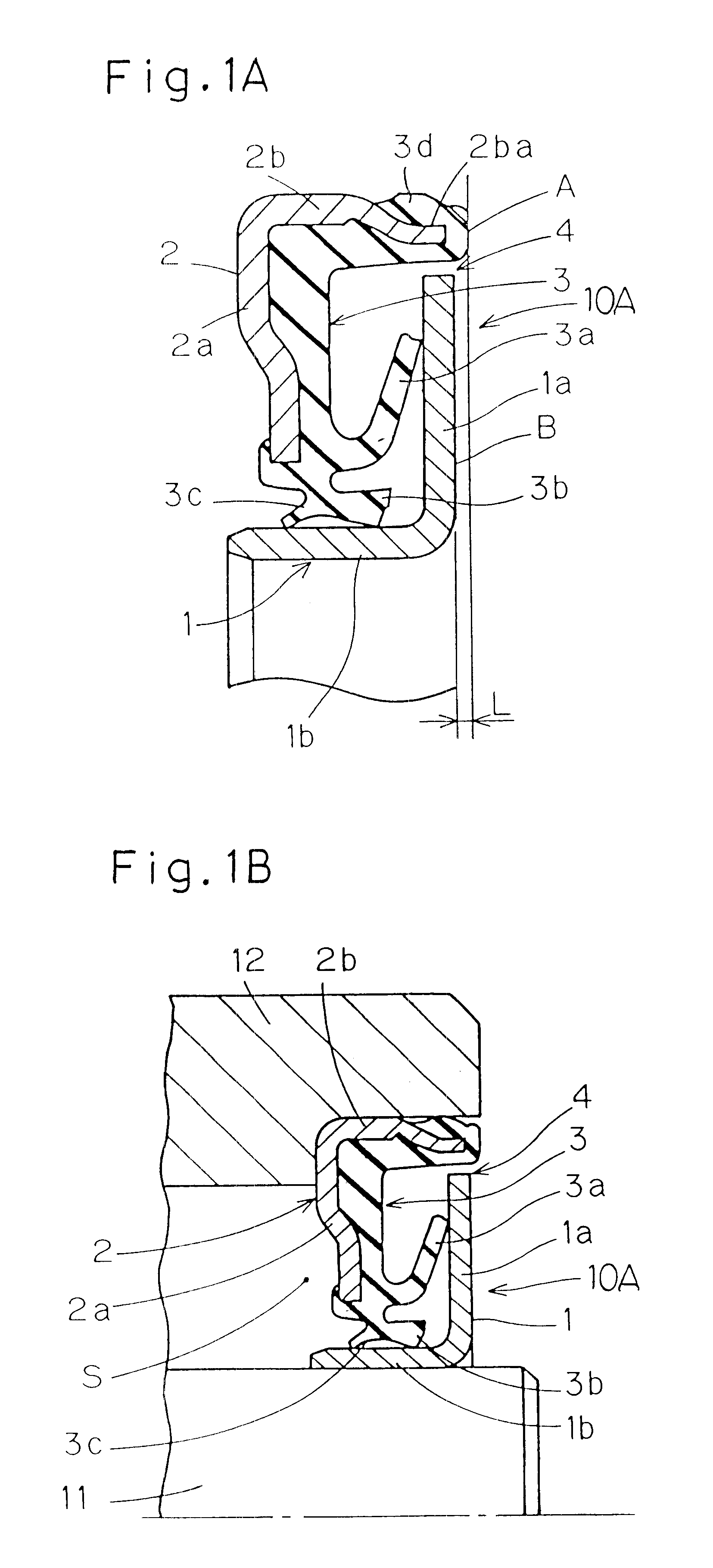
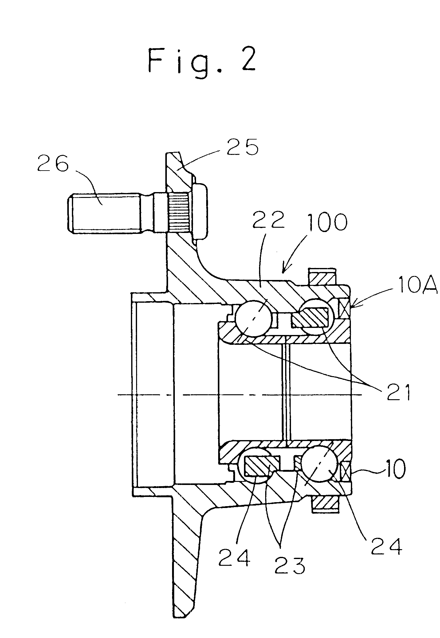
The first sealing plate 1 when mounted in between the inner and outer races 11 and 12 has its radial upright wall 1a positioned adjacent the respective ends of the inner and outer races 11 and 12 with a radial free end face of the radial upright wall 1a spaced a slight distance radially inwardly from an inner peripheral surface of the cylindrical wall 2b of the second sealing plate 2 to thereby define a labyrinth seal 4. An outer side surface B of the radial upright wall 1a of the first sealing plate 1 lies in a plane set back a distance L inwardly from a plane of an annular end face A of the cylindrical wall 2b of the second sealing plate 2. Where the cylindrical wall 2b of the second sealing plate 2 is covered by the elastic strip 3 as shown in accordance with the present invention, the inner peripheral surface and the annular end face A of the cylindrical wall 2b of the second sealing plate 2 are to be understood as represented by those of a portion of the elastic strip 3 that is...

second embodiment

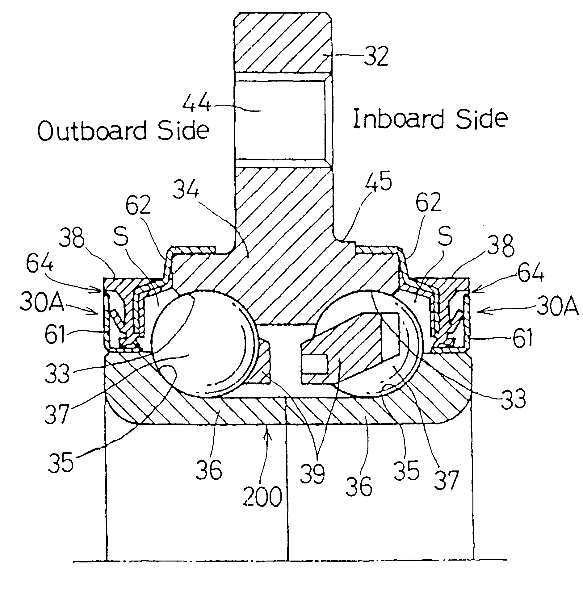
As can readily be seen from FIG. 4B, with the axle bearing 200 according to the present invention, surface areas of the cylindrical wall 61b and the upright wall 61a of the first sealing plate 61, with which the radial lips 38b and 38c and the side lip 38a of the seal lip member 38 are held in sliding contact, are protected by the labyrinth seal 64 to avoid ingress of muddy water and dusts. Consequently, those sliding surface areas are less susceptible to rusting, resulting in increase of the sealing performance. Also, since the first sealing plate 61 is made of stainless steel, any possible rusting of the sliding surface areas can be effectively prevented advantageously.

A third preferred embodiment of the present invention will now be described with reference to FIG. 5.

While in the foregoing second embodiment of the present invention, the first sealing plate 61 of the sealing device 30A has been used on the respective outer peripheral surfaces of the neighboring ends of the inner r...


PUM


Abstract

A sealing device for a bearing includes first and second annular sealing plates (1, 2) accommodated within an annular end space between inner and outer races (11, 12). Each of the first and second sealing plates (1, 2) is of a generally L-shaped section including a cylindrical (16, 26) wall and a radial upright wall (1a, 2a), and an elastic seal lip element (38). The first sealing plate (1) is secured with the radial upright wall (1a) thereof positioned adjacent respective end faces of the inner and outer races (11, 12), and the radial upright wall (1a) of the first sealing plate (1) has a free end remote from the cylindrical wall (1b) of the first sealing plate (1) spaced a predetermined distance from the cylindrical wall (2b) of the second sealing plate (2) to thereby form a radial gap (4). The radial upright wall (1a) of the first sealing plate (1) also has an outer side face (B) set back inwardly from a free end face (A) of the cylindrical wall (2b) of the second sealing plate (2).

Description

1. Field of the InventionThe present invention generally relates to a sealing device disposed between inner and outer races rotatable relative to each other such as, for example, between inner and outer races of a rolling bearing assembly or between inner and outer races that forms respectively a part of a rotary shaft and a part of a housing, for sealing an inner space between the outer and inner races from an external environment and, more particularly, to the sealing device for a bearing that utilizes a combination of a sealing plate such as a slinger and a sealing lip.2. Description of the Prior ArtHitherto, such a sealing device for an axle bearing as shown in FIG. 7 has been utilized. The sealing device 10 shown in FIG. 7 is used to seal an inner annular space between a fixed inner race and a rotatable outer race and includes an inner peripheral sealing plate 51 of a generally L-sectioned configuration and an outer peripheral sealing strip 52 of a generally L-sectioned configu...

Claims


Application Information

Patent Timeline
IPC IPC(8): B60B27/00F16C33/76F16J15/32
CPCF16C19/185F16C33/7879F16C33/7886F16J15/3264B60B27/02F16C2326/02
Inventor OHTSUKI, HISASHISUZUKI, SHOUGOTAJIMA, EIJI
Owner NTN CORP
Features
  • Generate Ideas
  • Intellectual Property
  • Life Sciences
  • Materials
  • Tech Scout
  • Unparalleled Data Quality
  • Higher Quality Content
  • 60% Fewer Hallucinations
Learn More