Device for press-fitting catalyzer core bed into outer case

a technology of catalytic converter and core bed, which is applied in the direction of catalyst carrier, physical/chemical process catalyst, separation process, etc., can solve the problem of not providing satisfied users

Inactive Publication Date: 2002-12-31
CALSONIC KANSEI CORP
View PDF6 Cites 3 Cited by
  • Summary
  • Abstract
  • Description
  • Claims
  • Application Information

AI Technical Summary

Problems solved by technology

However, the above-mentioned known technique has failed to provide the users with satisfied results for the following reasons.

Method used


Image

  • Device for press-fitting catalyzer core bed into outer case
  • Device for press-fitting catalyzer core bed into outer case
  • Device for press-fitting catalyzer core bed into outer case

Examples


first embodiment

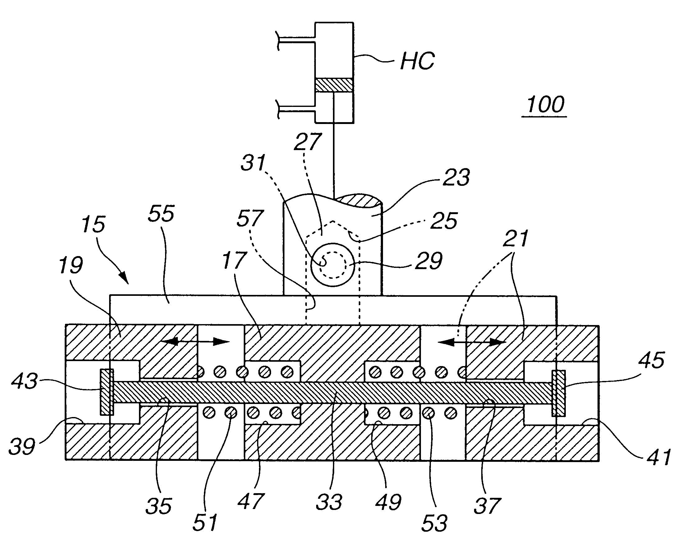
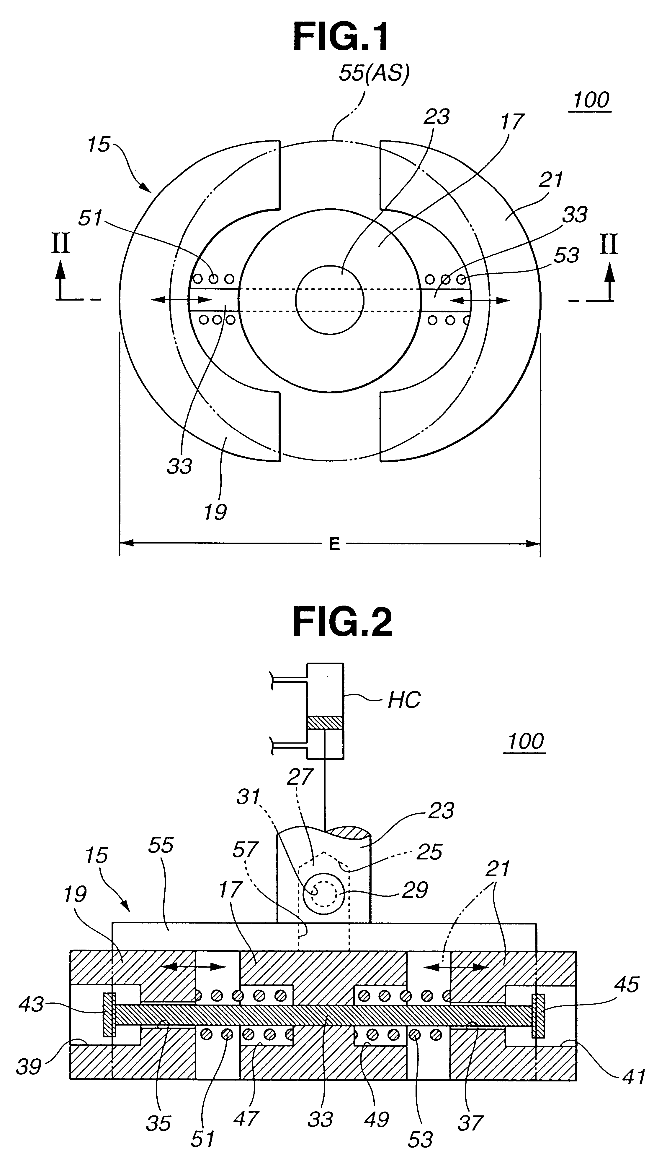
Referring to FIGS. 1 to 4, there is shown a fitting device 100 which is the present invention.

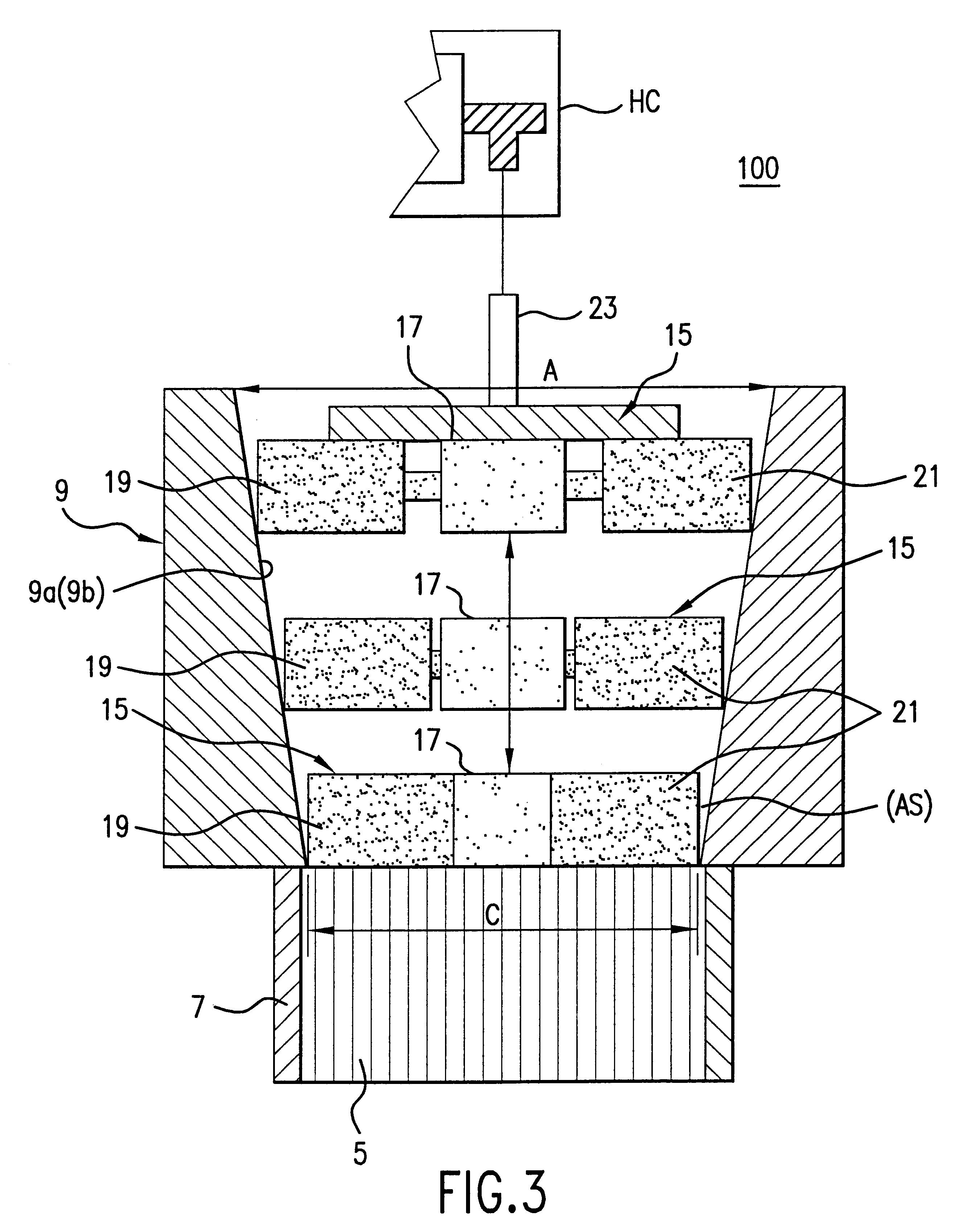
As is seen from FIG. 3, the fitting device 100 of this embodiment generally comprises a guide member 9 and a pressing member 15. It is to be noted that FIG. 3 shows three conditions or positions of the pressing member 15 in the guide member 9.

As is seen from FIG. 3, the guide member 9 is formed with a conical bore 9a, which is substantially the same as the above-mentioned known guide member 9 shown in FIGS. 14A and 14B. That is, the diameter "A" of the largest upper end of the bore 9a is larger than the diameter "C" of the smallest lower end of the bore 9a.

As is seen from FIGS. 1 and 2, the pressing member 15 comprises generally a circular center base plate 17, two arcuate side plates 19 and 21 arranged at diametrically opposed positions of the center base plate 17, a stay bolt 33 passing diametrically through the center base plate 17 to loosely hold the side plates 19 and 21 on its axially...

fifth embodiment

Referring to FIG. 9, there is shown, but partially, a fitting device 500 of the present invention.

In the pressing member 15-3 used in this embodiment, plate type members 65 are employed in place of the above-mentioned guide projections 61 and 63.

sixth embodiment

Referring to FIG. 10, there is shown a pressing member 15-4 used in a fitting device 600 of the present invention.

The pressing member 15-4 is substantially the same as the above-mentioned pressing member 15 (see FIG. 2) used in the first embodiment 100 except that in the sixth embodiment, two elastic rubber tubes 67 are used in place of the coil springs 51 and 53. In FIG. 10, members corresponding to the circular guide plate 55, the mounting rod 27, etc., (see FIG. 2) employed in the pressing member 15 are not shown.


PUM

PropertyMeasurementUnit
diameteraaaaaaaaaa
sizeaaaaaaaaaa
inclination angleaaaaaaaaaa

Abstract

In order to properly press-fit or thrust a cylindrical coiled body into a cylindrical case, a fitting device is provided. The fitting device comprises a guide member formed with a conical bore of which cross section gradually reduces with increase of a distance from a top of the bore toward a bottom of the same. The cross section of the bottom of the bore is slightly smaller than that of the coiled body. The guide member is coaxially put on the cylindrical case. The fitting device further comprises a pressing member which, when actuated, presses down the cylindrical coiled body raised in the bore thereby to thrust the raised coiled body into the cylindrical case through the bottom of the bore. The pressing member includes a center base plate, two side plates positioned on both sides of the center base plate, a guide structure by which the side plates are radially movable in opposite directions with respect to the center base plate, and biasing members for biasing the side plates radially outward.

Description

1. Field of the InventionThe present invention relates in general to devices for assembling catalytic converters, and more particularly to devices for press-fitting a cylindrical catalyzer core bed (or coiled body) into a cylindrical metal case.2. Description of the Related ArtIn order to clarify the task of the present invention, a known technique for press-fitting a cylindrical catalyzer core bed into a cylindrical outer case will be briefly described with reference to FIGS. 13 to 15 of the accompanying drawings. This technique is described in Japanese Patent First Provisional Publication 8-164487.FIG. 13 shows a method for producing a cylindrical catalyzer core bed (or coiled body) 5 that is a bed for catalyzer. As shown, a flat metal plate 3 and a corrugated metal plate 1 are put on one another and these overlapped plates 3 and 1 are coiled together to form a coiled body 5 which has a circular cross section as shown. After having a brazing foil of Ni (nickel) put around an axial...

Claims


Application Information

Patent Timeline
Patent Type & Authority Patents(United States)
IPC IPC(8): F01N3/28F01N7/18B01D53/86B23P19/02B01J32/00B01J35/02F01N13/18
CPCF01N3/2842F01N13/18Y10T29/5383
Inventor HAYASHI, TETSUJI
Owner CALSONIC KANSEI CORP
Why Eureka
Try Eureka