

Refrigerant cycle system with super-critical refrigerant pressure
- Summary
- Abstract
- Description
- Claims
- Application Information
AI Technical Summary
Benefits of technology
Problems solved by technology
Method used
Image

Examples
first embodiment
A first preferred embodiment of the present invention will be now described with reference to FIGS. 1-10. In the first embodiment, a super-critical refrigerant cycle of the present invention is typically applied to an air conditioner for heating.
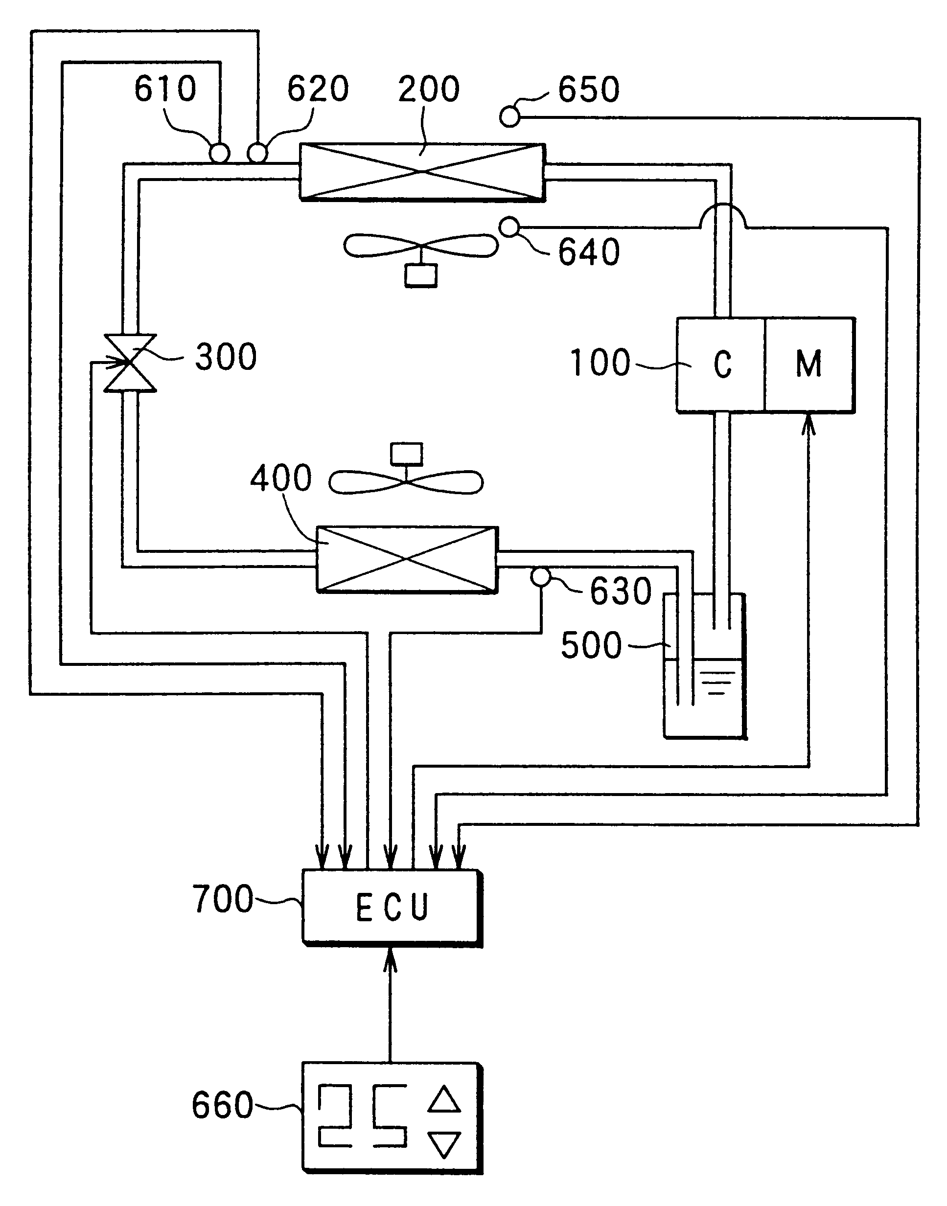
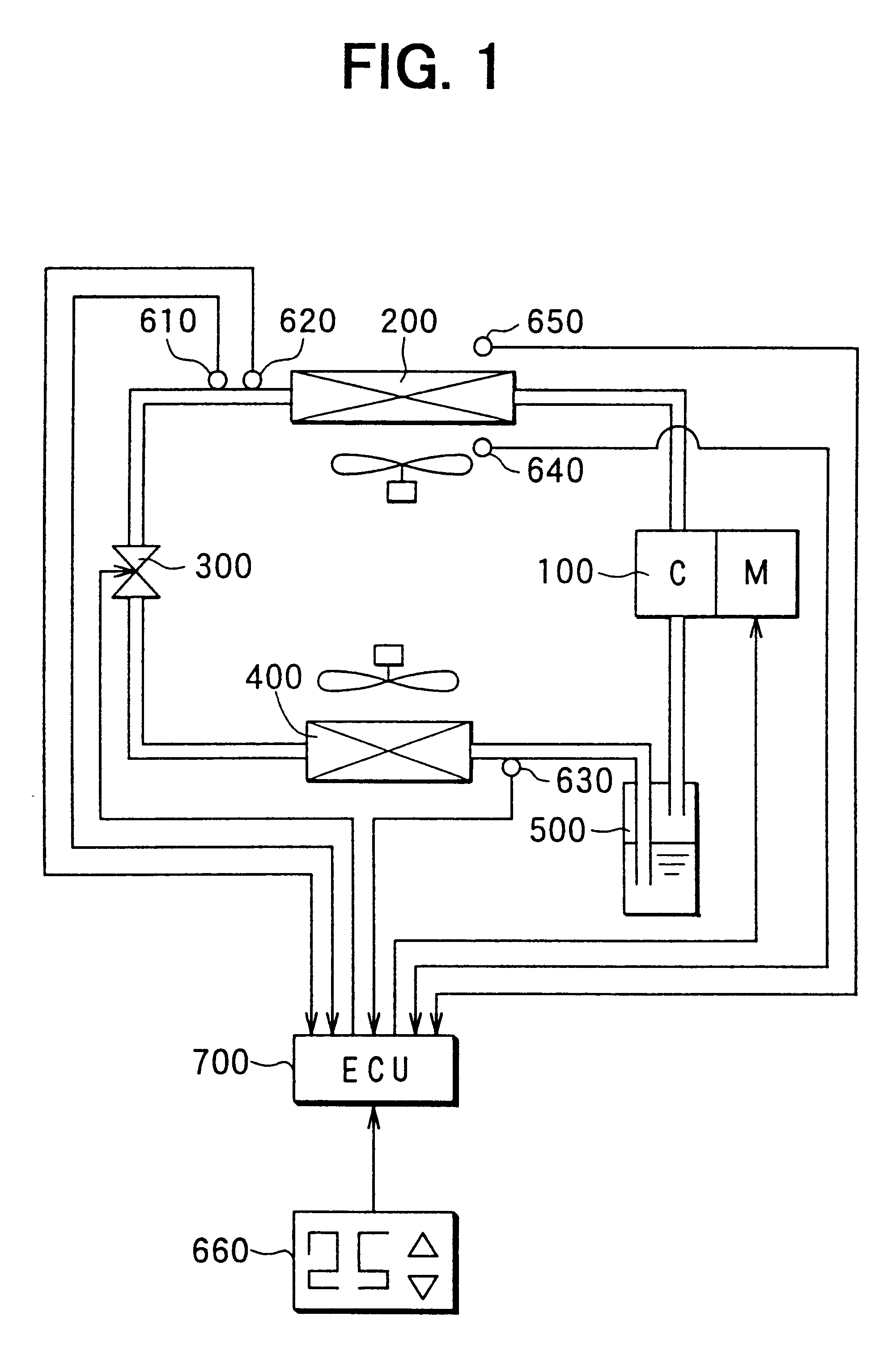
In FIG. 1, a compressor 100 for sucking and compressing refrigerant (e.g., carbon dioxide) is driven by a synchronous electrical motor M. In the first embodiment, as shown in FIG. 1, the compressor 100 and the electrical motor M are integrated to form an integrated electrical compressor. The electrical motor M is variably controlled by an inverter so that generation torque of the electrical motor M is controlled by current of the inverter and a rotation speed thereof is controlled by a current frequency of the inverter.
Refrigerant discharged from the compressor 100 flows into a radiator 200. Air passing through the radiator 200 is heated by performing a heat exchange between inside air inside a compartment and refrigerant flowing through the...
second embodiment
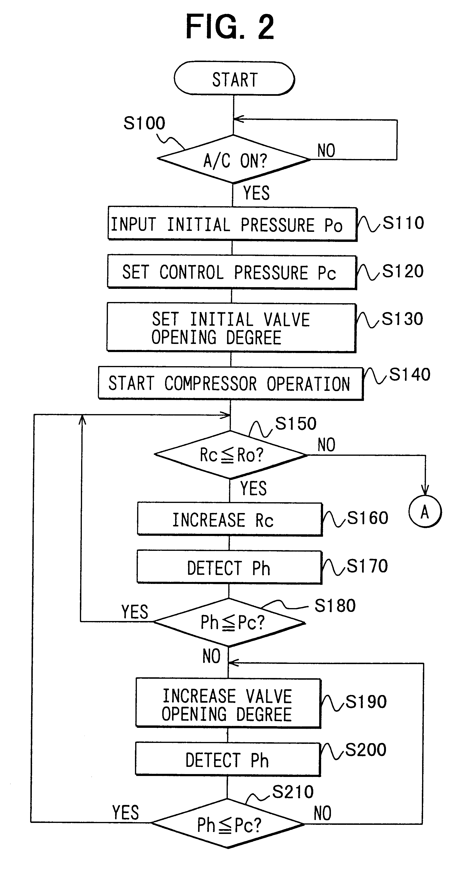
When it is determined that the pressure Ph of high-pressure side refrigerant at the outlet side of the radiator 200 is higher than the control pressure Pc at step S580 when the rotation speed of the compressor 100 is equal to or lower than the predetermined rotation speed Ro, the opening degree of the pressure control valve 300 is increased at step S590 so that the refrigerant pressure Ph at the outlet side of the radiator 200 detected by the first pressure sensor 620 at step S600 becomes equal to or smaller than the control pressure Pc. Further, it is determined whether or not the high-pressure side refrigerant pressure Ph is equal to or lower than the control pressure Pc at step S610, and the opening degree of the pressure control valve 300 is increased until the high-pressure side refrigerant pressure Ph is equal to or lower than the control pressure Pc. That is, in the second embodiment, in a case where the rotation speed of the compressor 100 is equal to or lower than the prede...
fourth embodiment
According to the present invention, the refrigerant amount discharged from the compressor 100 and the opening degree of the pressure control valve 300 are controlled, so that the effective efficiency .eta. of the refrigerant cycle becomes larger while the refrigerant temperature at the high-pressure side is made equal to or lower than the predetermined temperature Tdo. Accordingly, it can prevent the components of the super-critical refrigerant cycle from being troubled by heat, while the effective efficiency .eta. of the refrigerant cycle is increased.
A fifth preferred embodiment of the present invention will be now described with reference to FIGS. 18 and 19. In the above-described first embodiment, the super-critical refrigerant cycle is applied to the air conditioner for heating. However, in the fifth embodiment, a super-critical refrigerant cycle is typically applied to an air conditioner for cooling. In the super-critical refrigerant cycle of the fifth embodiment, inside air i...
PUM
 Abstract
Description
Claims
Application Information