Antenna device and its assembly method and wireless communication terminal and their assembly method
What is AI technical title?
AI technical title is built by Patsnap AI team. It summarizes the technical point description of the patent document.
an antenna device and assembly method technology, applied in the field of antenna devices and assembly methods, wireless communication terminals and assembly methods, can solve problems such as poor assembly
Inactive Publication Date: 2003-01-28
SONY CORP
View PDF11 Cites 35 Cited by
Summary
Abstract
Description
Claims
Application Information
AI Technical Summary
This helps you quickly interpret patents by identifying the three key elements:
Problems solved by technology
Method used
Benefits of technology
Problems solved by technology
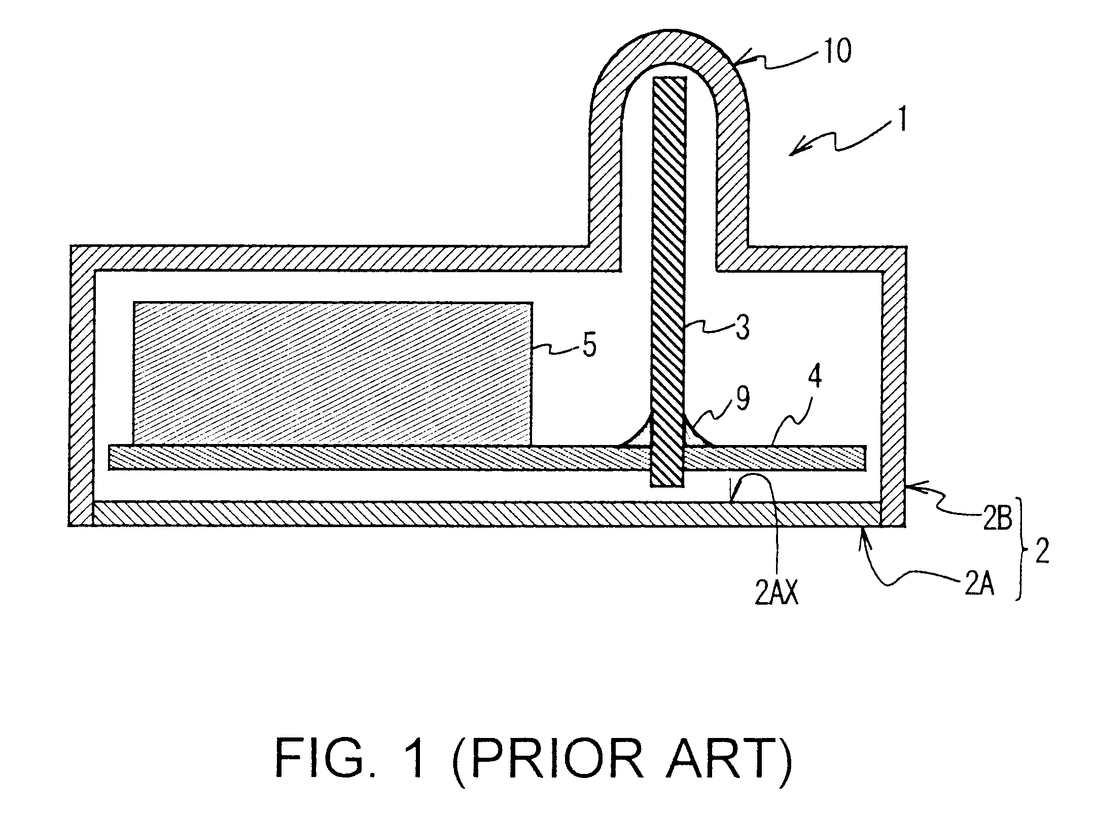
However, in assembling the wireless communication terminal 1 a worker holding the case half, top 2B can not see the antenna element 3 because of the case half, top 2B being a cover, making it hard to;have the other end of the antenna element 3 housed into the projection 10 and to mount the case half, top 2B, on the case half, bottom 2A, resulting in poor assemblage.
Method used
Image
Click on the blue label to locate the original text in one second.
Reading with bidirectional positioning of images and text.
Examples
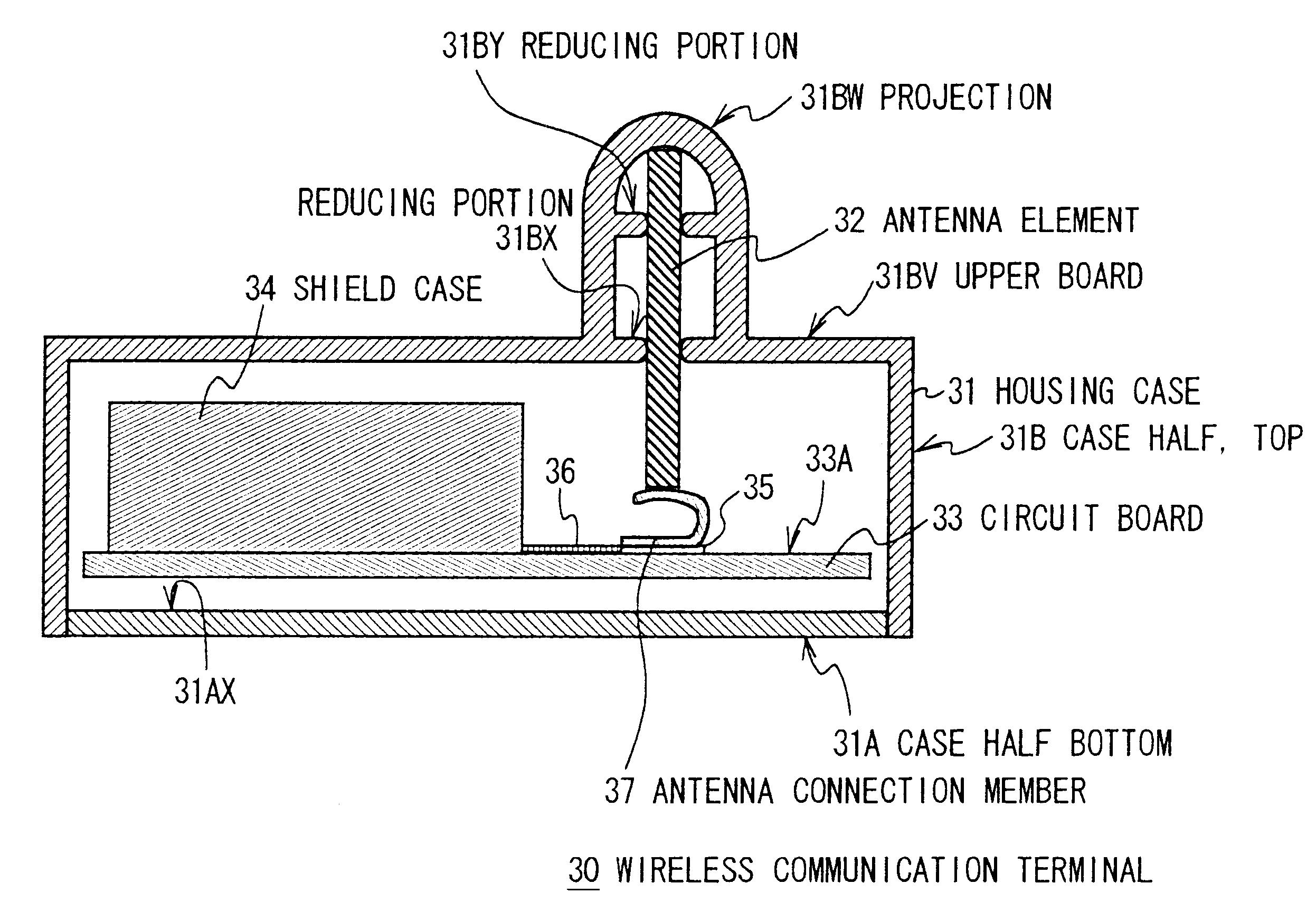
case 31
Housing case 31 consists of a case half, bottom 31A, and a case half, top 31B to be put on case half, bottom 31A.
With circuit board 33 fixed with shield case 34 located by means of legs (not shown in Fig.) case half, bottom 31A holds circuit board 33.
Then, on a surface 33A of circuit board 33 are formed a feeding point rand 35 in a given position in a form of a conductive: pattern, and a wiring pattern 36 electrically connecting feeding point rand 35 to TR circuit (not shown in Fig.) by means of a matching circuit (not shown in Fig.).
Also, feeding point rand 35 is installed, by the application of solder, with an antenna connection member 37 of a plate spring produced of a conductive plate such as a phosphoric copper, bent into a rough U shape by such a method as a pressing process.
Meanwhile, a cylindrical projection 31BW is placed on a upper board 31BV of case half, top 31B, facing towards an antenna connection member 37 mounted on circuit board 33 held onto case half, bottom 31A.
Fo...
case 51
Housing case 51 consists of a case half, bottom 51A and case half, top 51B made of a nonconductive material, with a projection 51BM formed around an upper flat portion 51BL of case half, top 51A.
Formed inside projection 51BM of case half, top 51B is an antenna guide 51BN protruding into the inside of case half, top 51B and pressed onto antenna connection member 37, and inside antenna guide 51BN are two reduced portions 51BO and 51BP in a. narrower internal diameter in double deck.
And, in case half, top 51B, one half portion of antenna element 52 placed between antenna guide 51BN, and reduced portions 51BO and 51BP in a way that antenna element 52 runs along antenna guide 51BN of projection 51BM, with the crooked other end of antenna element 52 pressed to the bottom of antenna guide 51BN.
As shown in FIG. 18, antenna element 52 is structured in a double-tier laminate with a conductive foil 52A formed in a meandering shape and a sheet of nonconductive transparent film 52B. One end of c...
PUM
Abstract
In an antenna device and its assembly method as well as a wireless communication terminal and its assembly method, an antenna element is held in an antenna holding member. A circuit board formed with an electrode to supply power to the antenna element is held on a board holding member. The antenna element and the electrode of the circuit board are electrically connected each other by means of a connection member having elasticity by fixing the antenna holding member on the board holding member. This enables the antenna holding member to be fixed on the board holding member easily because the antenna element is held in the antenna holding member in advance, and concurrently the antenna element can be electrically connected to the electrode of the circuit board by means of the connection member by merely fixing the antenna holding member on the board holding member, thus markedly enhancing the assembly of the antenna devices and wireless communication terminal units.
Description
1. Field of the InventionThe present invention relates to antenna device and its assembly method as well as wireless communication terminal and its assembly method, and more particularly, is suitably applied to wireless communication terminals to realize a network by wireless by connecting a variety of electronic equipment one another for example.2. Description of the Related ArtThere has been Local Area Network (LAN), a conventional network configured by connecting various electronic equipment to one another such as personal computers and printers, which are used within an architecture or on the premises.Various electronic devices are usually connected one another in such a LAN system by means of a dedicated communication cable. However, to dissolve complexity in routing the communication cable connecting such electronic devices, of late there:are cases where a wireless communication terminal is connected to each electronic device, thereby realizing wireless communication among tho...
Claims
Application Information
Patent Timeline
Application Date:The date an application was filed.
Publication Date:The date a patent or application was officially published.
First Publication Date:The earliest publication date of a patent with the same application number.
Issue Date:Publication date of the patent grant document.
PCT Entry Date:The Entry date of PCT National Phase.
Estimated Expiry Date:The statutory expiry date of a patent right according to the Patent Law, and it is the longest term of protection that the patent right can achieve without the termination of the patent right due to other reasons(Term extension factor has been taken into account ).
Invalid Date:Actual expiry date is based on effective date or publication date of legal transaction data of invalid patent.

