Tool, information processing unit, terminal unit, and management system

a technology of information processing unit and terminal unit, applied in the field of tools, can solve problems such as the tip portion of the driver becoming worn

Inactive Publication Date: 2011-03-24
MAX CO LTD
View PDF21 Cites 64 Cited by
  • Summary
  • Abstract
  • Description
  • Claims
  • Application Information

AI Technical Summary

Benefits of technology

[0026]Other features and advantage of the invention will be appear in description of embodiments and attached claims.

Problems solved by technology

Though parts constituting these tools have the predetermined durability, with increase in the number of actual driving of the fastener and passage of current-carrying time of a motor, a tip portion of a driver becomes worn, or impact absorption effect of a bumper which absorbs impact of a driver piston lowers.

Method used


Image

  • Tool, information processing unit, terminal unit, and management system
  • Tool, information processing unit, terminal unit, and management system
  • Tool, information processing unit, terminal unit, and management system

Examples


embodiment 1

[0054]

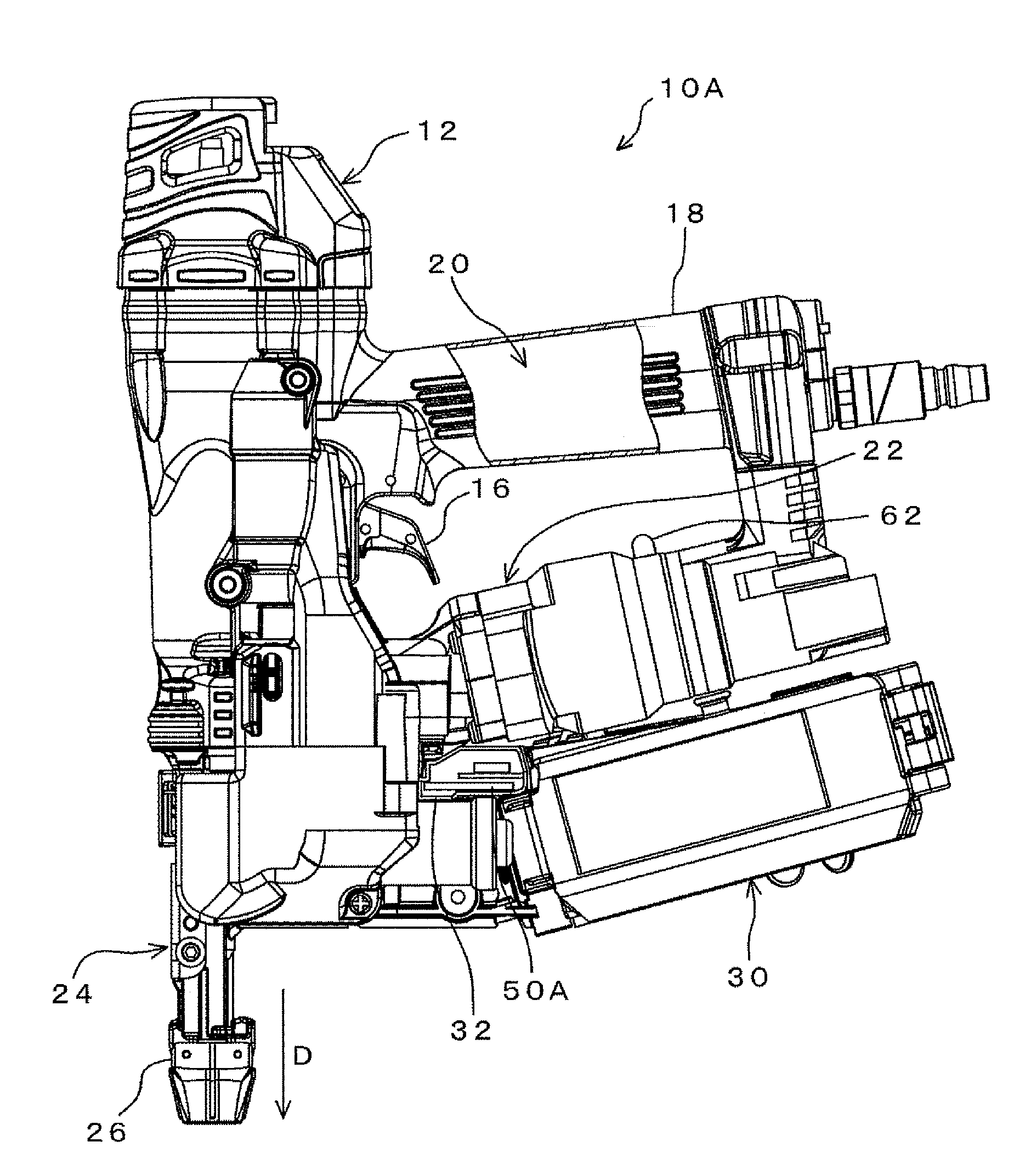
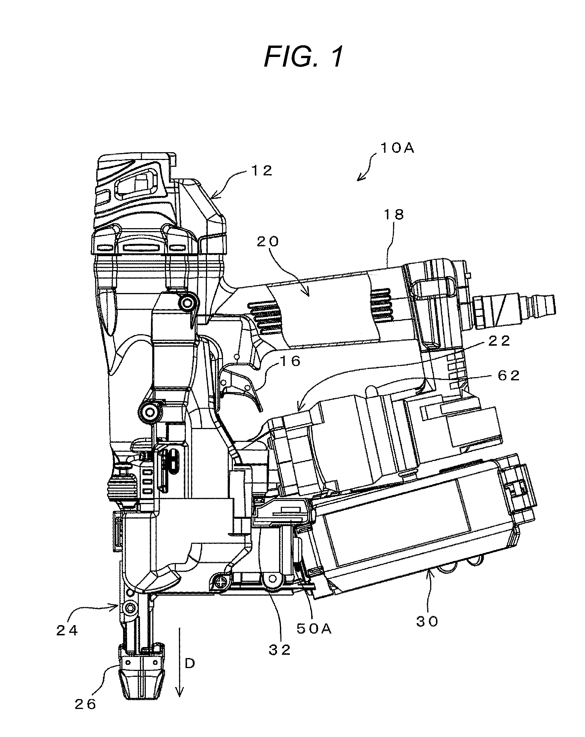
[0055]FIG. 1 is a diagram showing a configuration example of a pneumatic tool 10A according to a first embodiment of the invention. The pneumatic tool 10A includes a tool body 12 and a control substrate 50A. The tool body 12 includes a not-shown driving mechanism, a nose part 24, a contact part 26, and a not-shown screw-fastening mechanism. The driving mechanism includes a driving cylinder, a driving piston provided slidably in the driving cylinder, and a driver bit coupled integrally to the driving piston. As shown in FIG. 1, when a trigger 16 is operated, compressed air is supplied into the driving cylinder from an air chamber 20 which stores the compressed air therein, and the driver bit performs a driving operation. The air chamber 20 is formed inside a grip part 18.

[0056]The nose part 24 has an ejection port for ejecting a screw (fastener) to a member to be screwed. A contact part 26 functions a safety unit. The contact part 26 is arranged slidably at the nose part 24, an...

embodiment 2

[0086]Next, the configuration of an information processing unit 100 for reading out, from the control substrate 50A of the above-mentioned pneumatic tool 10A, the actual driving number of the pneumatic tool 10A will be described. The configuration of the pneumatic tool 10A which has been described in the above-mentioned first embodiment is omitted.

[0087]

[0088]The configuration of the information processing unit 100 for reading out, from the control substrate 50A of the pneumatic tool 10A, the actual driving number of the pneumatic tool 10A will be described. FIG. 7 is a perspective view showing a configuration example of the information processing unit 100. The information processing unit 100 includes a unit body 102 and a receiver 120. The unit body 102 and the receiver 120 are electrically interconnected through a cable 126.

[0089]The unit body 102 has a housing formed in the shape of a flat rectangular parallelepiped. On a housing surface, a display part 104 and an operational par...

embodiment 3

[0109]Next, a case where a power tool 10B is used in place of the above-mentioned pneumatic tool 10A will be described. Components common to the pneumatic tool 10A, the control substrate 50A and the like which have been described in the first embodiment are denoted by the same symbols, and detailed description of them are omitted.

[0110]

[0111]FIG. 11 shows the block configuration of the power tool 10B according to a third embodiment. The power tool 10B includes a control substrate 50B, a cell 66, a light emitting part 62, a sensor part 64, a motor 70, and a battery 72. The control substrate 50B includes a control part 54 configured by a CPU 56, a ROM 58 and a RAM 60; a memory part 48; a timer part 142; and plural I / F's 68.

[0112]The memory part 48 is composed of a nonvolatile semiconductor memory. In the memory part 48, data such as the maintenance time, the number of actual driving, and the number of oil filling are stored. The data becomes a criterion for giving warning for the moto...


PUM


Abstract

A sensor part detects an actual driving signal in the driving time by a pneumatic tool. A control part, based on the detected actual driving signal, makes an addition to the actual driving number which has already stored in a memory part to updates the actual driving number, and compares the updated accumulative actual driving number with the previously set basic maintenance number. As a result of the comparison, in case the accumulative actual driving number exceeds the basic maintenance number, it is determined that maintenance is necessary for the pneumatic tool. A light emitting part emits the light and blinks by an instruction from the control part, thereby to warn a user that the pneumatic tool is into the maintenance time. Hereby, the user can grasp the maintenance time of the tool surely and exactly.

Description

TECHNICAL FIELD[0001]The present invention relates to a tool, and particularly to a tool which determines maintenance time of the tool by detecting the current-carrying time of the tool or the number of actual driving of the tool, and notifies, when it has been determined that maintenance is necessary, a user about its fact.[0002]The invention relates to an information processing unit, and particularly to an information processing unit which receives by a light receiving part a light emission signal based on maintenance information which is emitted from a light emitting part of a tool, and displays the maintenance information in a display part.[0003]The invention relates further to a terminal unit and a management system, and particularly to a terminal unit and a management system in which specific information of a tool is stored in a storage part of the tool, and the specific information is read out from the storage part of the tool by means of the terminal unit and displayed in a ...

Claims


Application Information

Patent Timeline
Patent Type & Authority Applications(United States)
IPC IPC(8): B25B33/00G08B21/00
CPCB25B21/00B25B23/14B25F5/021B25F5/00B25D2250/101
Inventor NOBE, NOBUYUKIADACHI, MICHIAKITSUSHIMA, TSUTOMU
Owner MAX CO LTD
Why Eureka
Try Eureka