Method for initializing and allocating bandwidth in a permanent virtual connection for the transmission and control of audio, video, and computer data over a single network fabric

a technology of permanent virtual connection and network fabric, which is applied in the direction of data switching network, digital transmission, hybrid transportation, etc., can solve the problems of inability to meet the requirements of high-speed data transport, impediment to the transport of delay sensitive data, and economic feasibility of deployment to the desktop today, so as to ensure the quality of service

Inactive Publication Date: 2003-03-25
NETWORK 1 TECH
View PDF14 Cites 156 Cited by
  • Summary
  • Abstract
  • Description
  • Claims
  • Application Information

AI Technical Summary

Problems solved by technology

The circuit switched nature and limited bandwidth of this network cannot support today's high-speed data transport requirements.
However, the packet nature of these networks presents an impediment to the transport of delay sensitive data such as real-time audio or video, with the exception of ATM, which is not economically feasible to deploy to the desktop today.
However, the prior art has not fully addressed the integration of telecom and data in the context of the requirements of a small to mid-size office, typically having personal computers, workstations, servers, printers, etc., connected through Unshielded Twisted Pair (UTP) cable in a LAN using standards-compliant packets such as Ethernet, and also having a Digital Key / Hybrid Telephone System with telephone handsets connected to the Common Equipment Unit (CEU) by a separate UTP cable system.
Unfortunately, contention between real-time audio and / or video applications and computer file transfer applications for access to the LAN segment causes a problem with real-time transmissions.
This contention causes unacceptable latencies to be encountered by packets carrying delay sensitive data, queued waiting to enter the media, while file transfer packets are using the media.
The latency caused by the transmission of these maximum size packets rapidly consumes the Round-Trip Echo Path Delay specification of 2.0 ms for Digital to Digital Connections in a Digital Key / Hybrid telephone system.
Packet collisions on the media caused by the asynchronous transmissions from multiple station devices attached to the media require the retransmission of corrupted packets.
This process of detecting collisions and re-transmitting packets increases the latency for all packets traversing the network.
Packet collisions and the resulting increased latency become a significant problem in poorly designed or over-subscribed networks (i.e., networks improperly deployed or networks with too many users per segment).
Therefore, working in a Switched Ethernet environment may greatly improve, but does not eliminate, the problem of having multiple station devices generating independent, and in this case incompatible, traffic streams over the same LAN segment.
Packet queuing delays within the Ethernet Switch also add latency to packet transmissions producing an additional impairment to providing a guaranteed QoS for delay sensitive data.
When a number of smaller packets are queued behind a longer packet, then FIFO queuing results in a larger average delay per packet than if the shorter packets were transmitted before the longer packets.
However, traffic from different flows interfere with one another and just adding a priority FIFO queue does not isolate the behavior of each traffic flow.
However, the incremental resolution of the traffic flow control is limited to a discrete packet base.
Mixed simultaneous traffic flows of large packets carrying computer file transfer information and small packets carrying delay sensitive information, on a limited bandwidth port (e.g., 10 Mbps), still present an impairment to providing a guaranteed QoS for the delay sensitive information.

Method used


Image

  • Method for initializing and allocating bandwidth in a permanent virtual connection for the transmission and control of audio, video, and computer data over a single network fabric
  • Method for initializing and allocating bandwidth in a permanent virtual connection for the transmission and control of audio, video, and computer data over a single network fabric
  • Method for initializing and allocating bandwidth in a permanent virtual connection for the transmission and control of audio, video, and computer data over a single network fabric

Examples


Embodiment Construction

Overall Description

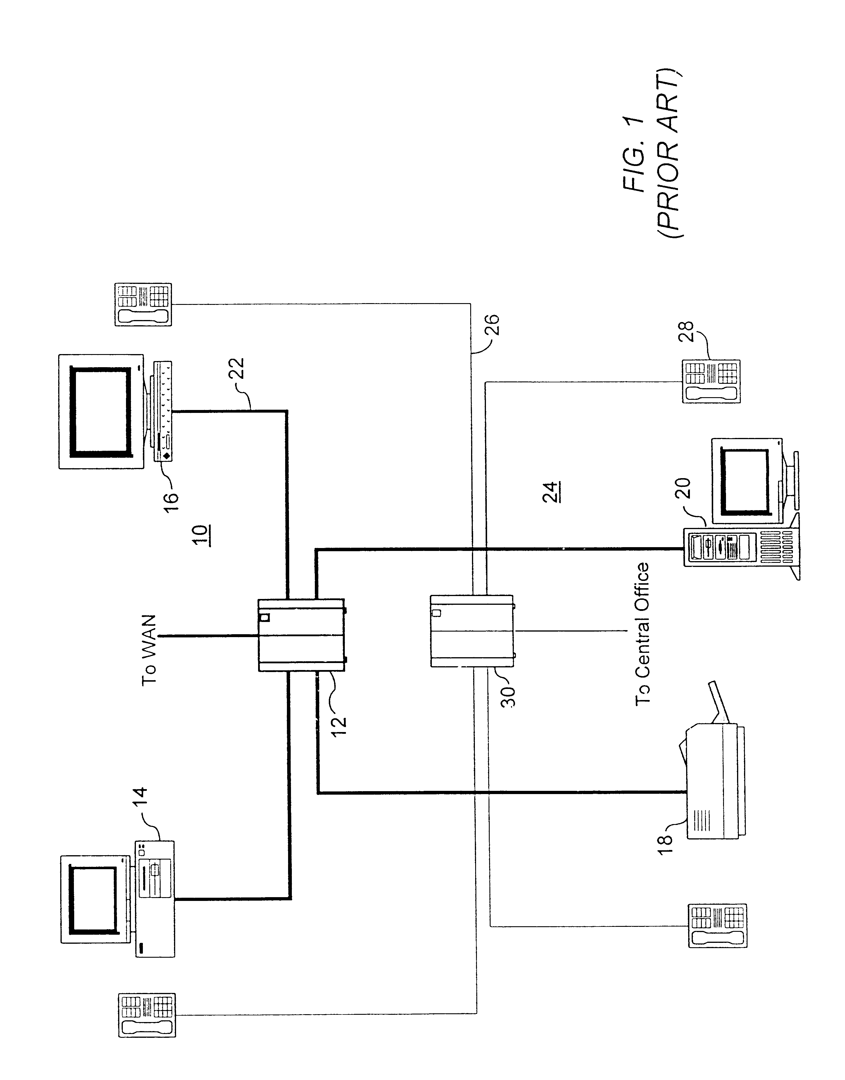
FIG. 1 illustrates a prior art arrangement of a typical small office having an Ethernet LAN shown generally at 10 connected in "Star Wiring Topology" from an Ethernet hub 12 to a PC 14, workstation 16, printer 18 and server 20 with Unshielded Twisted Pair (UTP) cable 22. A separate traditional digital key / hybrid office telecommunications system, illustrated generally at 24, is connected by UTP cable 26 in a similar "Star Wiring Topology" to digital key telephone instruments such as 28, which access the central office from Common Equipment Unit (CEU) 30.

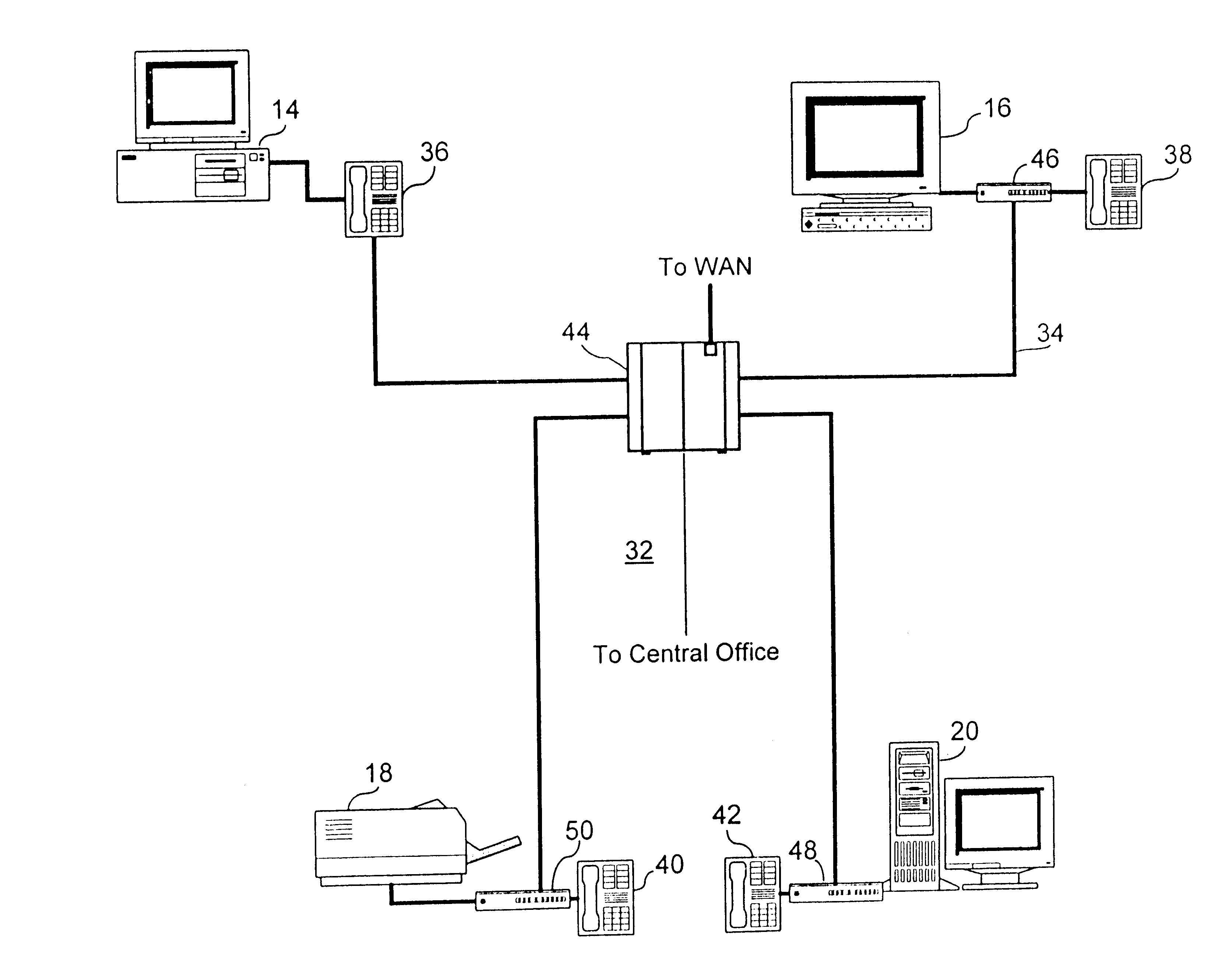
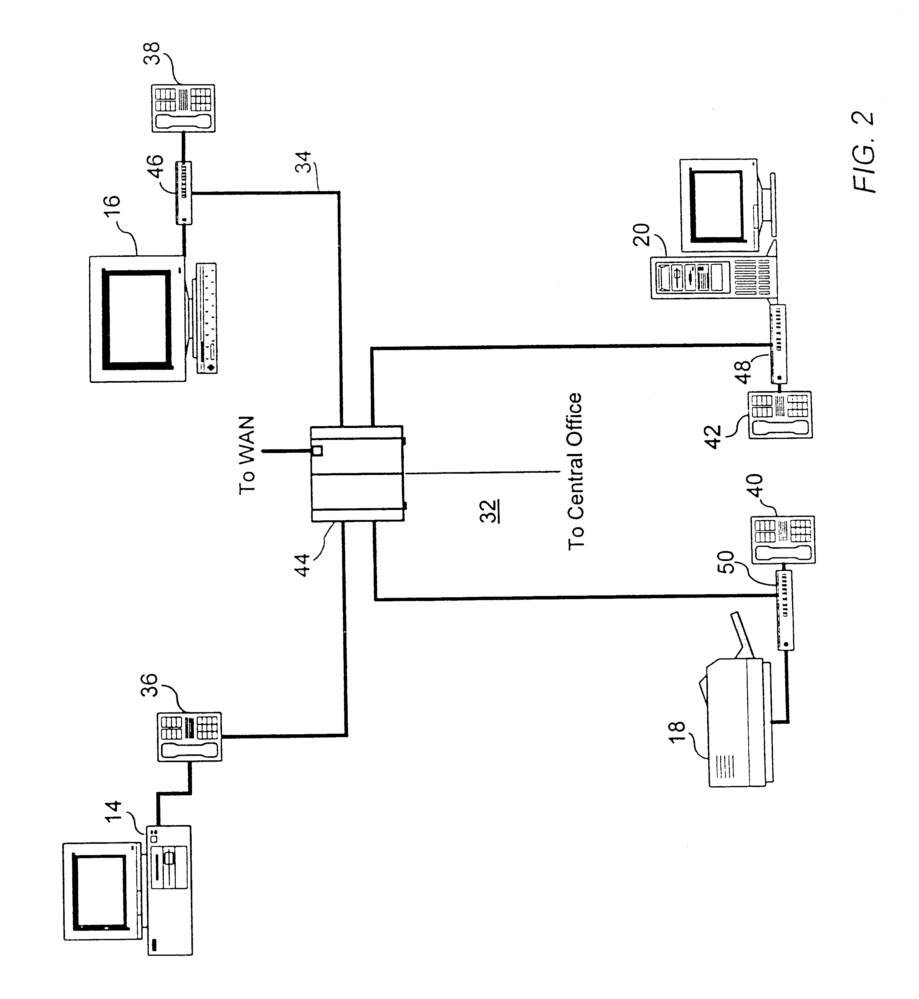
In accordance with the present invention, illustrated in simplified form in FIG. 2, a single network shown generally at 32 for integrated transmission and control of audio, video and computer data is connected in "Star Wiring Topology" over UTP cable 34 to assorted user terminal equipment, such as the previously described PC 14, workstation 16, printer 18 and server 20, as well as to modified Digital Key Telephone i...


PUM


Abstract

A permanent virtual connection (PVC) is automatically set up over an Ethernet local area network (LAN) link between a work station device having a digital telephone and a Communications Switching Module (CSM) when the device is first connected to the LAN. The PVC is established by exchange of information in standard Ethernet packets between the device and the CSM. Automatic reservation of a full duplex PVC for digital telephone signaling and control information enables set up and break down of voice channels within the same PVC by exchange of signaling information in standard Ethernet packets.

Description

This invention relates to the field of telecommunications and data communications over a network and, more particularly, to initializing and allocating bandwidth in a permanent virtual connection suitable for integrated voice and data communications over a local area network.Today, the typical office communications infrastructure consists of two independent networks: the telecommunications network and data communications network. The telecommunications network provides circuit switched channels with limited bandwidth (typically 64 Kbps to 128 Kbps). The circuit switched nature and limited bandwidth of this network cannot support today's high-speed data transport requirements. The office data communications network provides packet transport (Ethernet or Token Ring) via hubs and / or switches and, to a much lesser degree, cells in Asynchronous Transfer Mode (ATM). These data communications networks provide bandwidths to the desktop of 10 Mbps to 100 Mbps. However, the packet nature of t...

Claims


Application Information

Patent Timeline
Patent Type & Authority Patents(United States)
IPC IPC(8): H04L12/56H04L12/64H04L12/413H04L12/407H04M7/00
CPCH04M7/006H04L12/413H04L12/6418H04L47/10H04L47/13H04L47/2416H04L49/351H04L12/40013H04L49/205H04L49/254H04L49/3027H04L2012/644H04L2012/6443H04L2012/6454H04L2012/6459H04L2012/6475H04L2012/6481H04L12/4035
Inventor KEENAN, RONALD M.BARRAZA, THOMAS F.CACERES, EDWARD R.DEPTULA, JOSEPH A.EVANS, PATRICK A.SETARO, JOSEPH
Owner NETWORK 1 TECH
Why Eureka
Try Eureka