Water mixing system for water heaters

a water heater and water mixing technology, applied in lighting and heating equipment, process and machine control, instruments, etc., can solve problems such as disturbing the water temperature gradien

Inactive Publication Date: 2003-04-29
BRADENBAUGH KENNETH A
View PDF12 Cites 34 Cited by
  • Summary
  • Abstract
  • Description
  • Claims
  • Application Information

AI Technical Summary

Problems solved by technology

The velocity and uneven distribution of water discharging from the dip tube often result in streamers of cold water flowing upwardly in the tank, disturbing the water temperature gradient and sometimes allowing cold water to discharge from the hot water outlet.

Method used


Image

  • Water mixing system for water heaters
  • Water mixing system for water heaters
  • Water mixing system for water heaters

Examples


Embodiment Construction

which follows is made with reference to the drawings and in terms of preferred embodiments of the invention. The detailed description is not intended to limit the scope of the present invention, and the only limitations intended are those embodied in the claims appended hereto.

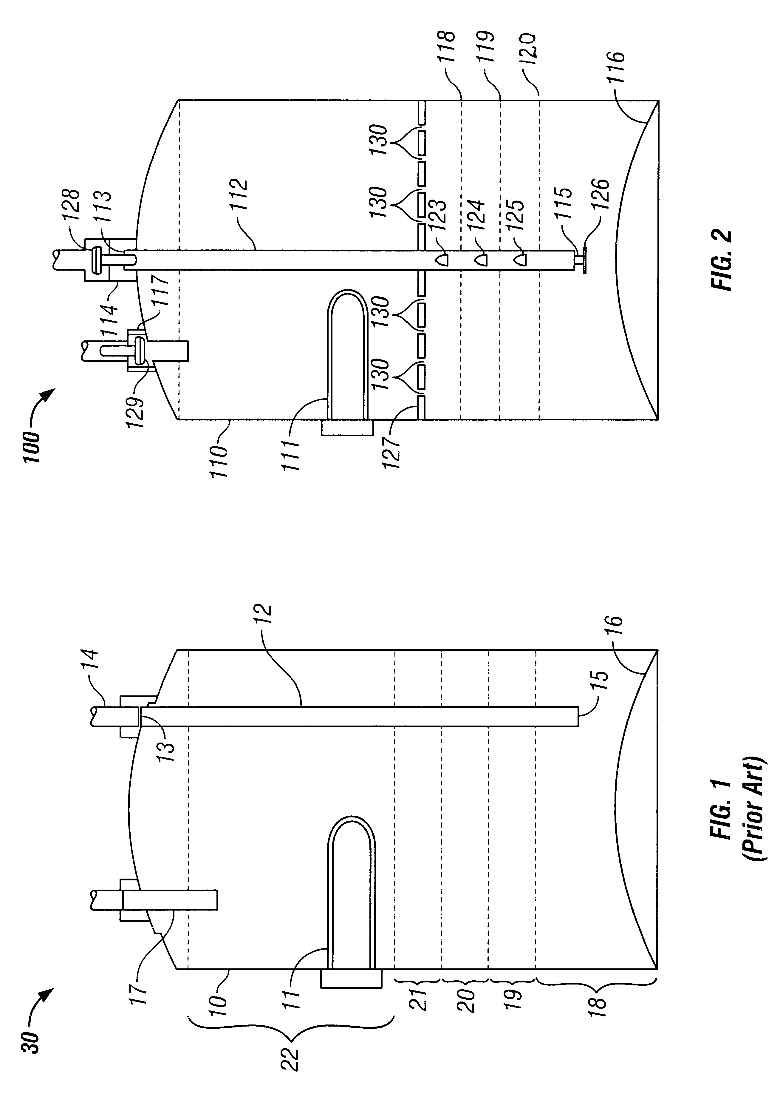
In FIG. 1, a conventional water heater is shown and its operation is described below for presenting problems which the improvements of the present invention overcome.

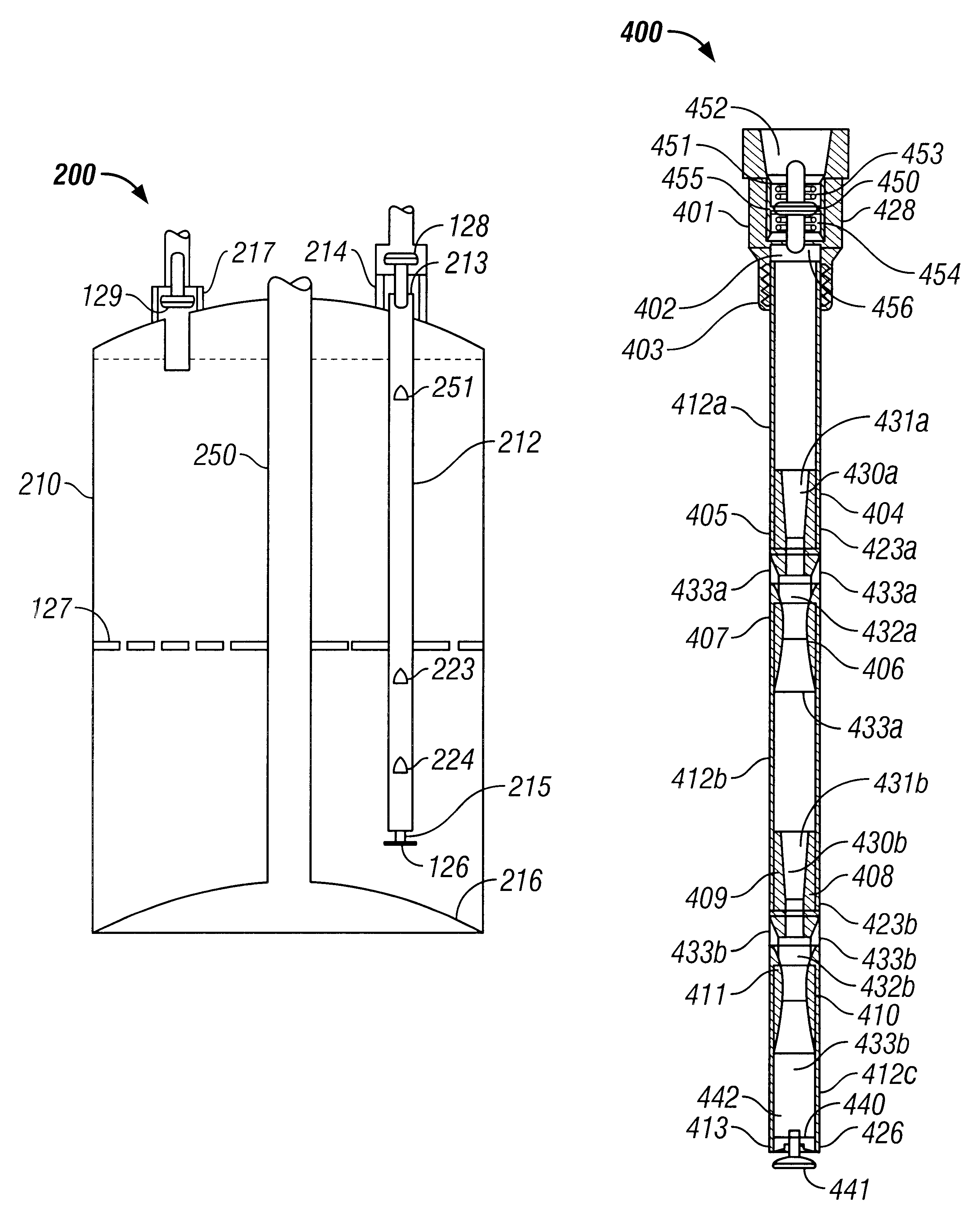
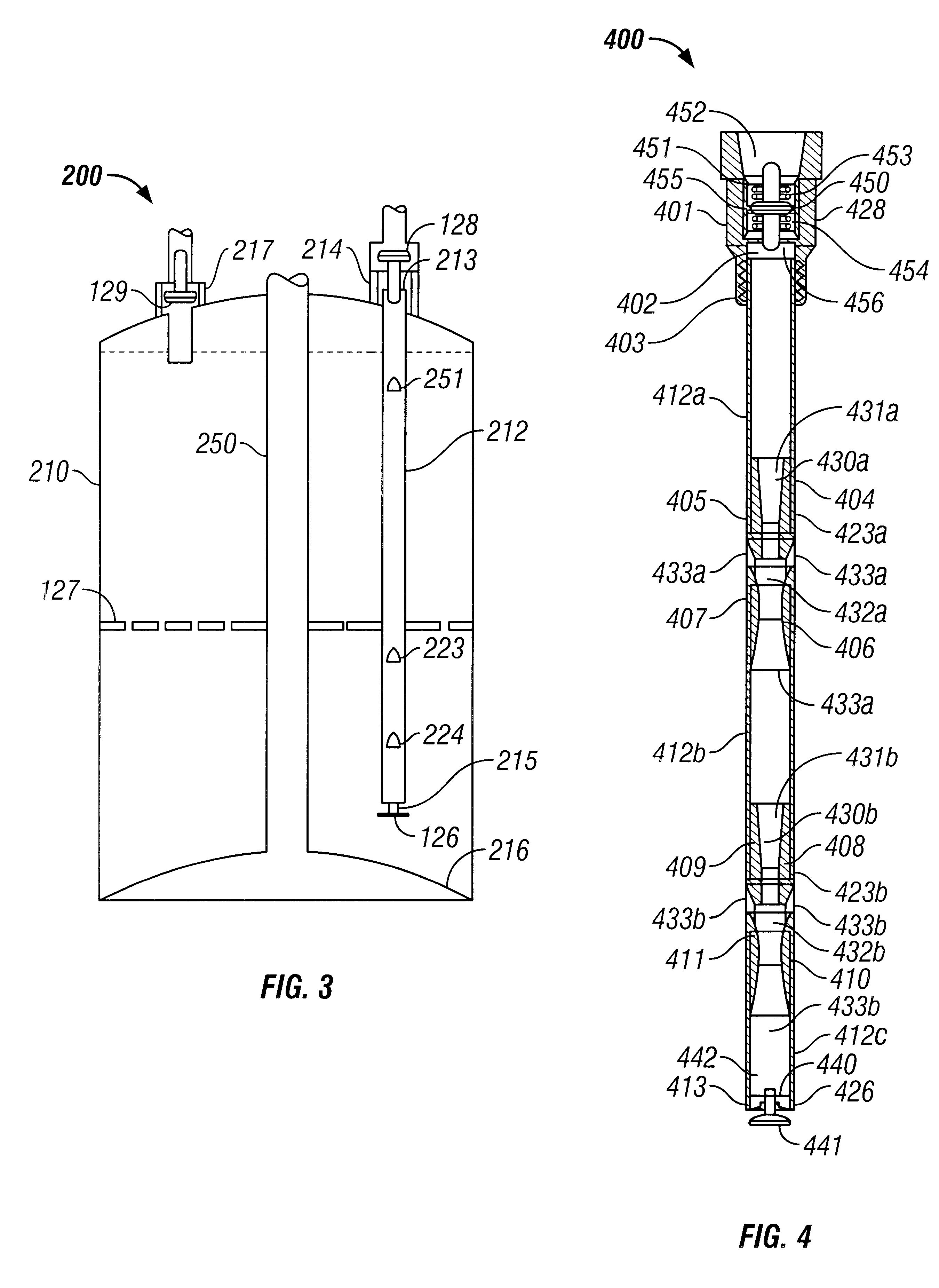
In FIG. 1, a conventional electrically heated tank type water heater 30 is shown in schematic cross section. Water heater 30 comprises a water tank 10 having an electrical resistance heating element 11, a cold water inlet 14 and a hot water outlet 17. A cold water dip tube 12, having an open upper end 13 connected to cold water inlet 14, is disposed substantially vertically in water tank 10 and terminates at open end 15 near the bottom 16 of tank 10. In operation, hot water is withdrawn from water tank 10 via hot water outlet 17. Cold water, prope...


PUM


Abstract

Disclosed herein are storage type water heaters having means for improved mixing of cold water supply with water stored in the water tank of a water heater, means for limiting surges of water into and out of a water tank, and means for disrupting formation and propagation of convection currents and water streamers in a water tank.

Description

1. Field of the InventionThe present invention relates to storage type water heaters. Particularly, the present invention relates to improved apparatus and methods for distributing water in the water storage tank of a water heater for improving thermal efficiency. More particularly, the present invention relates to improved methods and apparatus for mixing incoming cold water with heated water in the water storage tank for eliminating stratification of water according to temperature and for preventing intrusion of cold water streamers into the heated water in the upper portion of the water storage tank.2. Description of Pertinent ArtStorage type water heaters, as contemplated herein, typically comprise a vertical, cylindrical water rank having a cold water supply tube, (commonly referred to as a "dip tube"), extending internally from the top of the water tank to a point near the bottom of the water rank, and having a hot water outlet near the top of the water tank, Such water heater...

Claims


Application Information

Patent Timeline
Patent Type & Authority Patents(United States)
IPC IPC(8): F24H1/18F24H9/12
CPCF24H1/18F24H9/124F28D2020/0086Y10T137/6497F24H9/133
Inventor BRADENBAUGH, KENNETH A.
Owner BRADENBAUGH KENNETH A
Why Eureka
Try Eureka