Multi-function farm implement for treating soil

a multi-functional, farm implement technology, applied in the field of farm equipment, can solve the problems of soil compaction, affecting crop yield, and affecting crop yield, and achieve the effect of reducing crop yield, reducing crop yield, and avoiding scalding and rocks

Inactive Publication Date: 2003-04-29
TILLAGE MANAGEMENT
View PDF15 Cites 88 Cited by
  • Summary
  • Abstract
  • Description
  • Claims
  • Application Information

AI Technical Summary

Problems solved by technology

Multiple passes with different implements as described above do not necessarily provide a level seedbed with a consistent depth and can cause compaction of the soil, especially moist soil.
Compaction of soil can reduce crop yields.
During the multiple passes with different implements, the implement being used typically bounces and rocks as it is pulled across the field.
As a second implement is pulled through the field thereafter, the second implement will also rock and bounce as it is being pulled, because the field had been non-uniformly treated by the first implement.
Thus, the cultivation depth of each implement is likely to be different and the conditioning of the soil provided by the implements is likely to be non-uniform because of the above-described conditions.
As is also apparent, attempting to set different separately operated implements such that they operate at the exact same depth is likely to be very difficult if not impossible.
Therefore, the use of multiple passes with multiple implements to prepare a level seedbed with a consistent depth is impractical in most instances.
Further, the multiple-pass, multiple implement techniques described above do not allow for efficient incorporation of fertilizer or fumigants or the like into a seedbed.
More particularly, if a fertilizer or seed is applied to the top of the soil and not incorporated within a particular period of time, the effectiveness of the fertilizer or fumigants can be lost.
Therefore, fertilizer or the like applied between passes of an implement can result

Method used


Image

  • Multi-function farm implement for treating soil
  • Multi-function farm implement for treating soil
  • Multi-function farm implement for treating soil

Examples


Embodiment Construction

Reference will now be made in detail to the presently preferred embodiments and methods of the invention as illustrated in the accompanying drawings, in which like reference characters designate like or corresponding parts throughout the drawings. It should be noted, however, that the invention in its broader aspects is not limited to the specific details, representative devices and methods, and illustrative examples shown and described in this section in connection with the preferred embodiments and methods. The invention according to its various aspects is particularly pointed out and distinctly claimed in the attached claims read in view of this specification, and appropriate equivalents.

It is to be noted that, as used in the specification and the appended claims, the singular forms "a," "an," and "the" include plural referents unless the context clearly dictates otherwise.

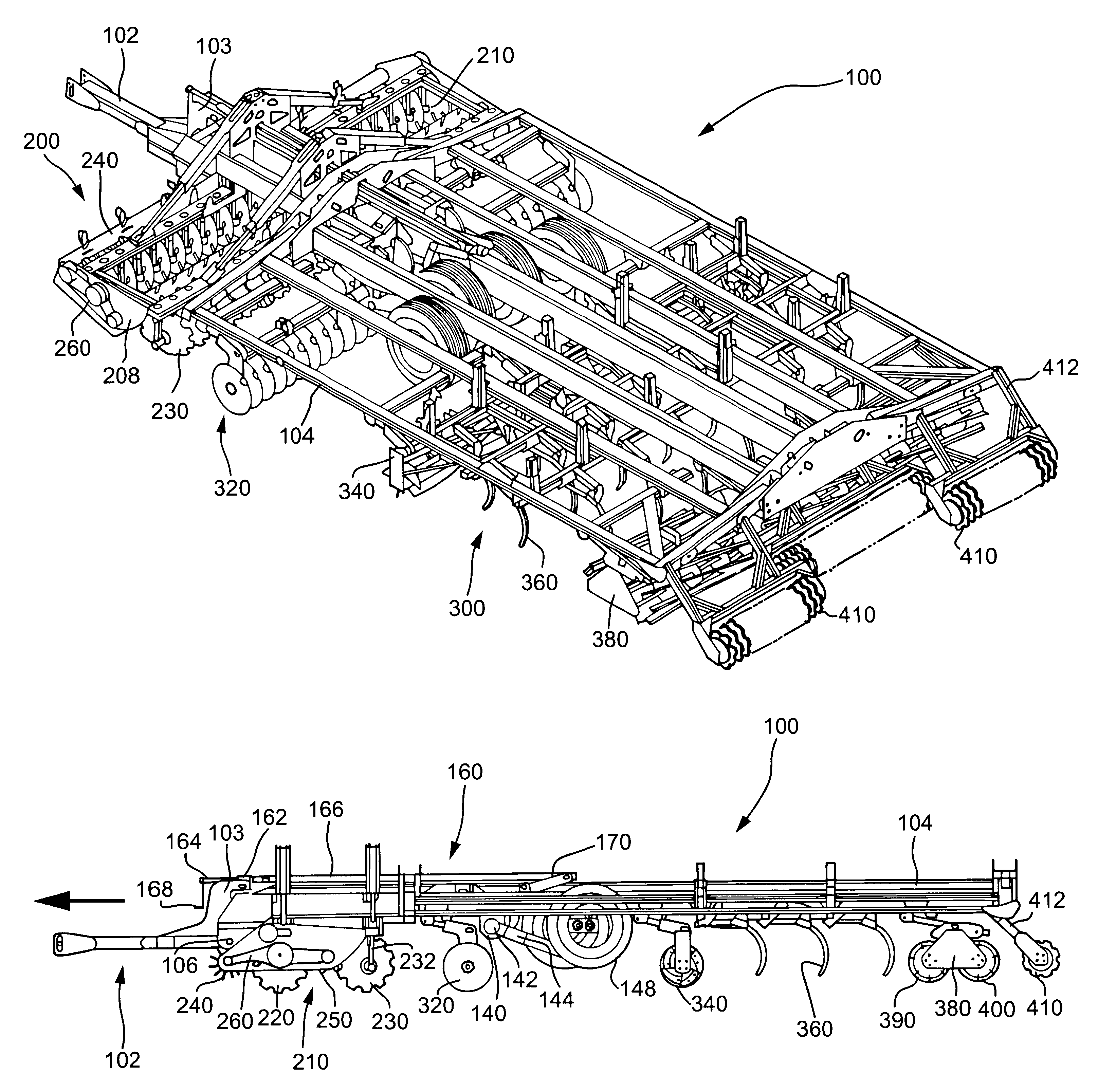
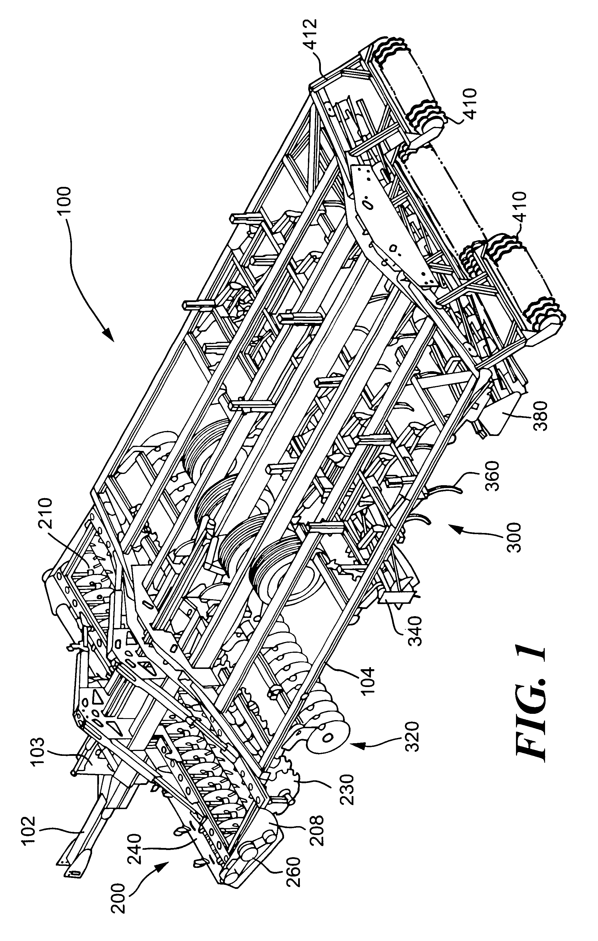
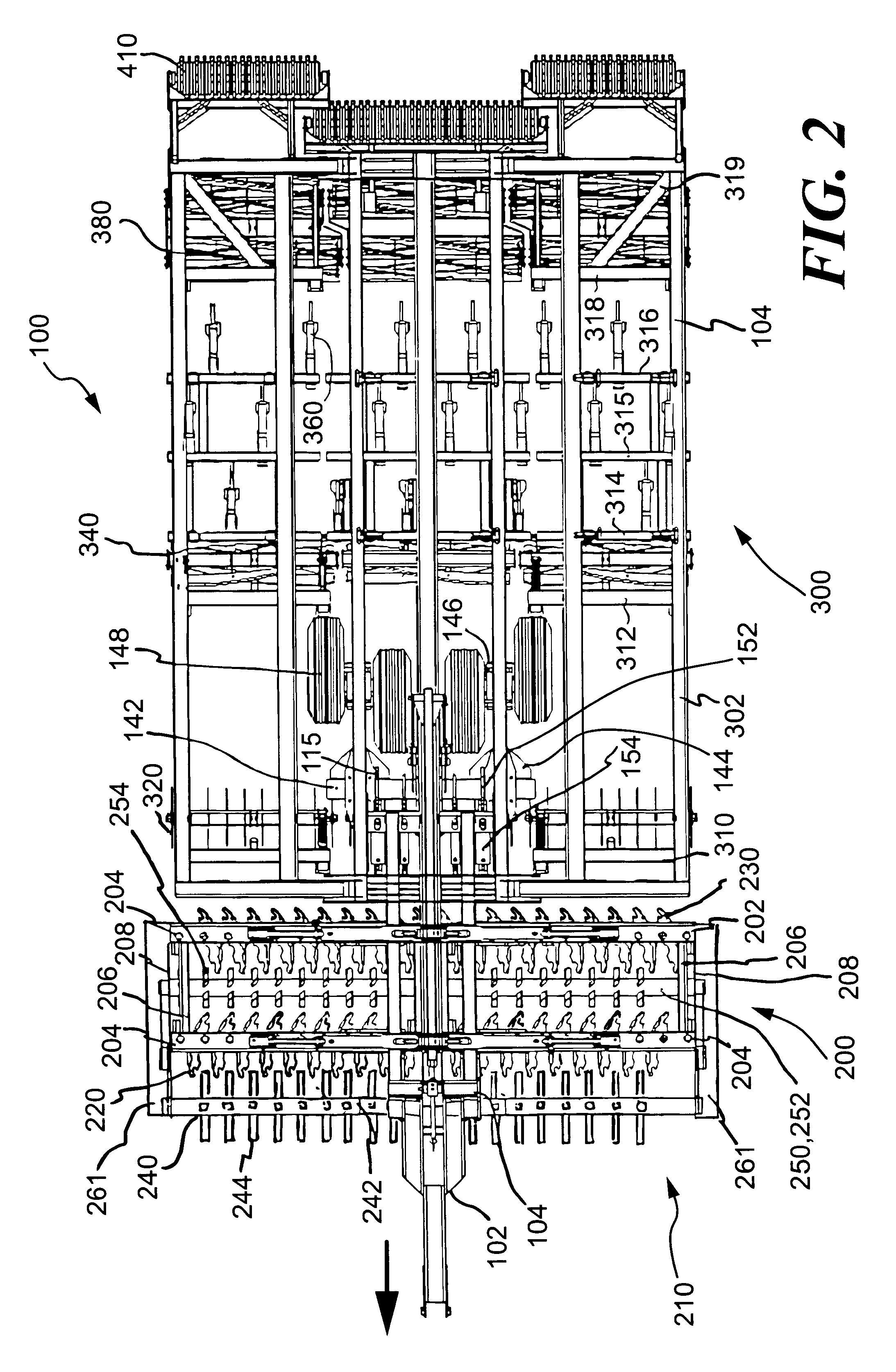
Turning now to the drawings in greater detail and initially to FIGS. 1-3, a farm implement of the present in...


PUM


Abstract

The farm implement of this invention is movable across ground along a direction of travel for tillage. The farm implement includes at least a frame and a disc/drive unit. The disc/drive unit includes first and second pluralities of discs, each having a ground-engaging outer periphery defining a plane angled acutely relative to the direction of travel. The first discs are angled to an opposite side of the direction of travel than the second discs. Positioned in front of the first discs is a ground-engaging driver rotatably coupled to the frame for rotating as the driver engages and is moved across the ground along the direction of travel. A driven flow controller is rotatably coupled and situated between the plurality of first discs and the plurality of second discs. The ground-engaging driver is operatively controlling and preferably accelerating the rotational speed of the driven flow controller.

Description

1. Field of the InventionThis invention relates to the field of farm equipment for breaking and mixing soil, especially for preparing a seedbed for planting. Particularly preferred aspects of the invention relate to the field of farm implements having multiple cultivating devices that manipulate the soil in distinct ways to collectively form a level seedbed with a consistent depth by a single pass of the implement. This invention further relates to the planting of crops and incorporation of fertilizers and herbicides into a seedbed.2. Description of the Related ArtFarmers for years have been searching for an implement that would allow them to convert compacted soil into a level seedbed with a consistent depth for providing excellent conditions for planting of a crop. It is also desirable for grass or stubble growing or disposed on top of the soil to be worked into and uniformly through the seedbed so that it does not interfere with a planting implement passing through the seedbed.Fa...

Claims


Application Information

Patent Timeline
IPC IPC(8): A01B25/00A01B49/00A01B49/02
CPCA01B49/027A01B25/00
Inventor MCDONALD, KEVIN G.
Owner TILLAGE MANAGEMENT
Why Eureka
Try Eureka