Rocker-type power-supply switch device

a power-supply switch and rocker-type technology, applied in the field of switch, can solve the problems of many parts being needed and parts being difficult to assembl

Inactive Publication Date: 2003-05-06
ALPS ALPINE CO LTD
View PDF4 Cites 18 Cited by
  • Summary
  • Abstract
  • Description
  • Claims
  • Application Information

AI Technical Summary

Benefits of technology

In one aspect of the invention, a switch comprises a first case and a second case. The first case has an accommodating portion that receives a stationary contact and a movable contact. A cover, having a window hole, is supported by a top portion of the first case. An operating lever that includes a portion passing through the window hole operates a movable contact. The movable contact mechanically couples and separates from a stationary contact. At an outside portion of the second case, a hook such as an engaging hook, and a stationary terminal project from the first case. The first case and the cover are received by the second case. In this aspect, the first case and the cover are comprised of an arc resistance resin. The second case is comprised of a thermoplastic resin. Preferably, the second case is more flexible than the first case. Furthermore, the stationary terminal is secured to the second case through a receiving hole by a press fitting. Preferably, the receiving hole passes through an inside bottom portion of the first case.
In a second aspect, a contact section, which comprises the stationary contact and the movable contact, is enclosed by the first case and the cover. An outside surface of the first case and an inside surface of the second case comprise a preventing means. A recess formed within an outside side surface of the first case, and a protrusion projecting from the inside surface of the second case preferably comprise the preventing means.
In another aspect, the switch comprises a protruding step which is positioned near an inside bottom surface of the second case. The protruding step is disposed near a hole configured to receive the stationary terminal. Preferably, a through hole passes through the inside bottom portion of the first case. The through hole is positioned to receive the protruding step. In this aspect, the stationary terminal is positioned within the switch by bringing a bottom surface portion of the stationary terminal into contact with the protruding step. In another aspect, the first case and the second case is positioned by fitting the protruding step through the through hole.

Problems solved by technology

In these switches, many parts may be needed and these parts may be difficult to assemble.

Method used


Image

  • Rocker-type power-supply switch device
  • Rocker-type power-supply switch device
  • Rocker-type power-supply switch device

Examples


Embodiment Construction

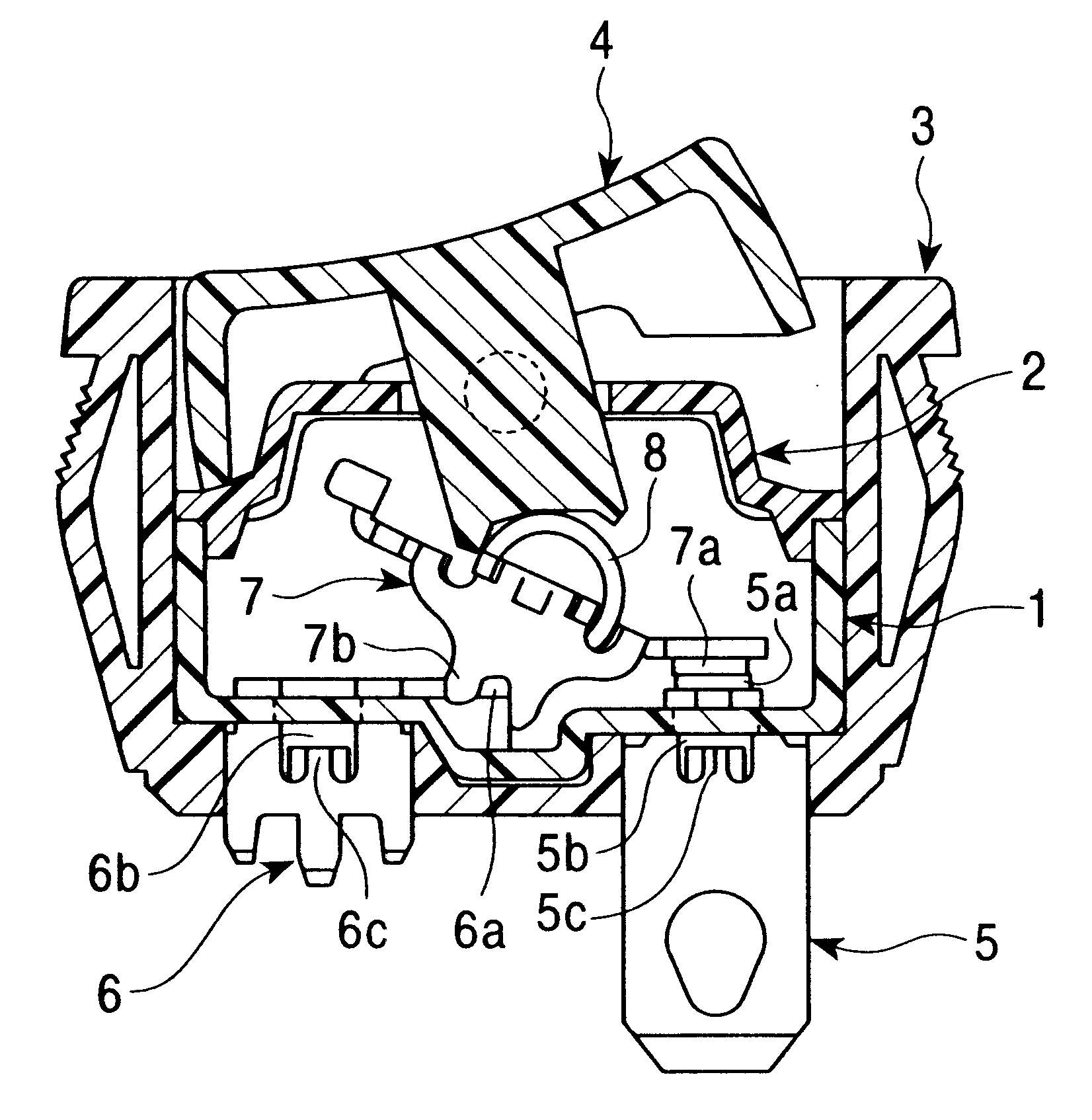
Referring to FIGS. 1-12, a first case 1 is comprised of an insulating material, that preferably includes a plastifiable PPS (polyphenylene sulfide) having an arc resistance and a thermosetting resin such as unsaturated polyester. Preferably, the plastifiable PPS has a high arc resistance.

The first case 1 includes an open topside. As shown in FIG. 7, preferably an interior portion of the first case 1 is separated into two accommodating portions 1b and 1c by an insulating wall 1a. A pair of substantially rectangular slot-shaped receiving holes 1d are positioned near the corners of the first case 1. The substantially rectangular slot-shaped receiving holes 1d are configured to receive stationary terminals 5 and 6 that are shown in FIG. 3. The stationary terminals 5 and 6 are positioned in an interior bottom portion of the accommodation portions 1b and 1c. Preferably, the substantially rectangular slot-shaped receiving holes 1d are positioned across from each other. A pair of substantia...


PUM


Abstract

A switch device includes a first case and a second case. Stationary contacts are enclosed within the first case that is sealed by a cover. An operating lever configured to actuate a movable contact is partially received by a window hole within the cover. An engaging hook is unitary part of or is coupled to the outside surface of the second case. Stationary terminals project from the stationary contacts. The second case encloses the first case and the cover. The first case and the cover are made of resins having an arc resistance. The second case is made of a thermoplastic resin that is more flexible than the first case.

Description

1. Field of the InventionThe present invention relates to a switch, and more particularly, to a seesaw-type power-supply switch.2. Description of the Related ArtTo mount some conventional switches to power supplies, the conventional switches engage an outer case of the power supplies through hooks. These hooks can be made of a flexible material, such as thermoplastic resin. When arc resistance is needed, the switch case can be made of a thermosetting resin. In some designs, the hooks are made of plate materials that connect to the switch case.When a thermosetting resin is used, the hook, in some instances, is made separately from the switch case. In these switches, many parts may be needed and these parts may be difficult to assemble. Accordingly, there is a need for an easily assembled switch that has an arc resistance.In one aspect of the invention, a switch comprises a first case and a second case. The first case has an accommodating portion that receives a stationary contact and...

Claims


Application Information

Patent Timeline
Patent Type & Authority Patents(United States)
IPC IPC(8): H01H23/04H01H23/08H01H23/00
CPCH01H23/08H01H23/04
Inventor TAKEDA, MASAYUKIMORI, TOSHIHARU
Owner ALPS ALPINE CO LTD
Why Eureka
Try Eureka