Portable camping tent structure with built-in overhead electric fan and power source

Inactive Publication Date: 2002-06-04
JENNINGS HARRY G
View PDF3 Cites 107 Cited by
  • Summary
  • Abstract
  • Description
  • Claims
  • Application Information

AI Technical Summary

Problems solved by technology

When camping, heat and humidity in tents are common problems.
However, the common portable fan moves little air in a tent and thus fails to cool the occupants.
Common portable fans fail to exchange enough air to remove excess humidity.
There are other disadvantages of c

Method used


Image

  • Portable camping tent structure with built-in overhead electric fan and power source
  • Portable camping tent structure with built-in overhead electric fan and power source
  • Portable camping tent structure with built-in overhead electric fan and power source

Examples


Embodiment Construction

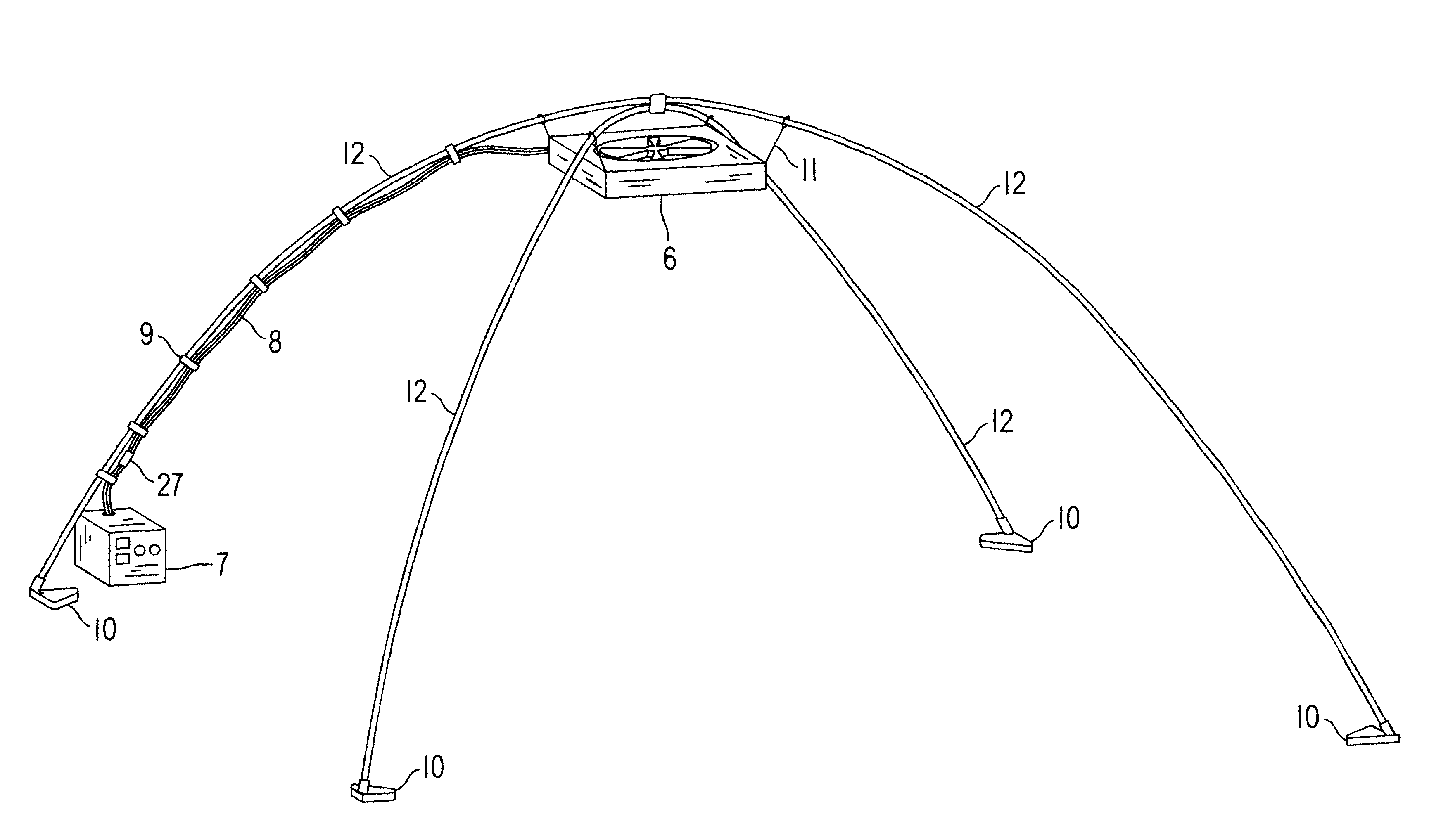
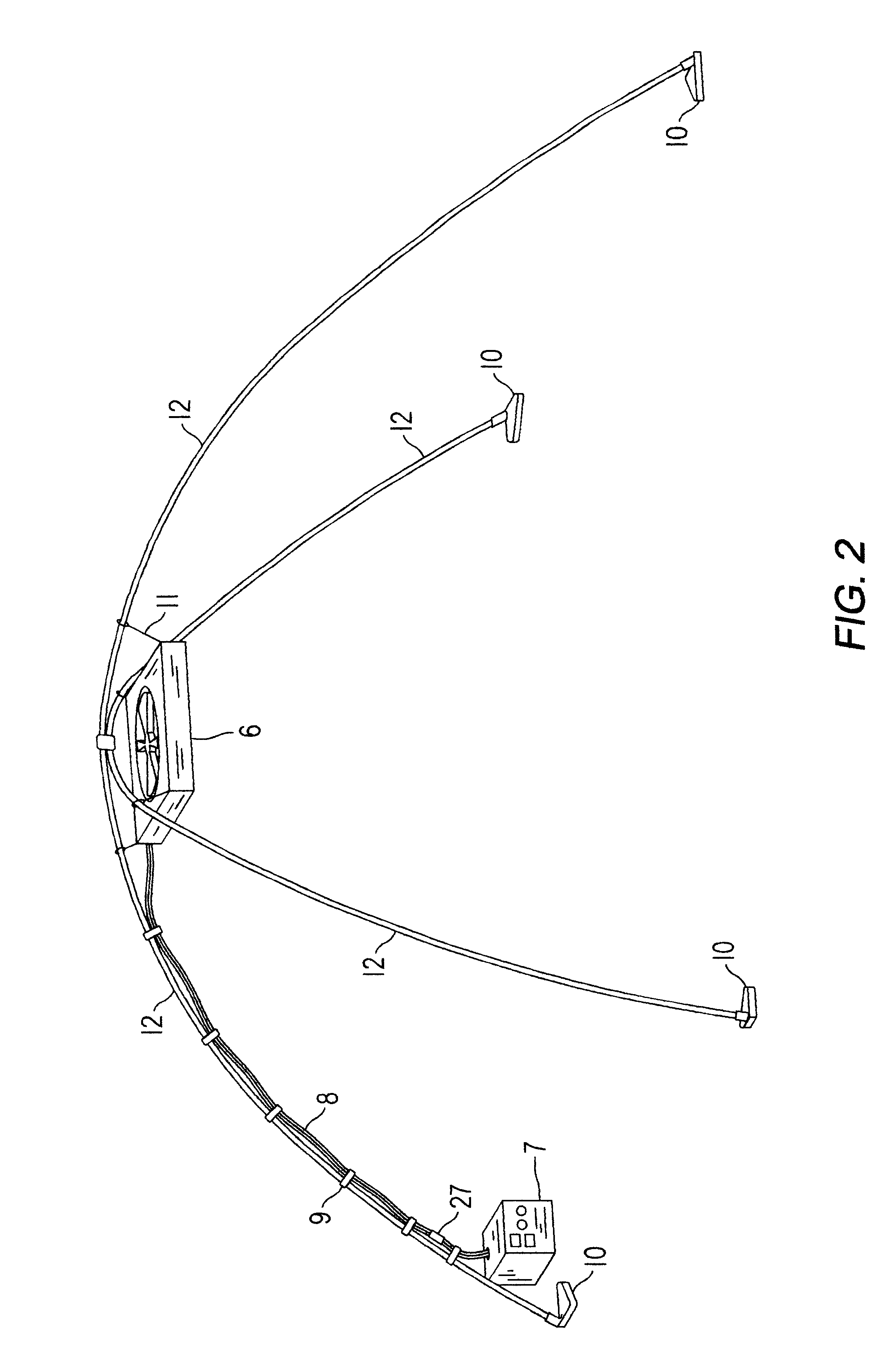
A preferred embodiment of the present invention is illustrated in FIGS. 1, 2, and 3. As seen in these figures a fan and light unit 6 can be neatly and securely mounted inside of a standard square dome camping tent. The fan and light unit is easily powered by a portable power supply and control unit 7. With this invention it becomes easy and convenient to cool a camping tent and remove the excess humidity. The power supply and control unit 7 can also be used to power other items that are commonly used while camping. The power supply and control unit 7 can be easily recharged by plugging it directly into a common 110V power source, through the charging system of an automobile, or adapted to be recharged by solar power.

FIG. 4--Additional Embodiments

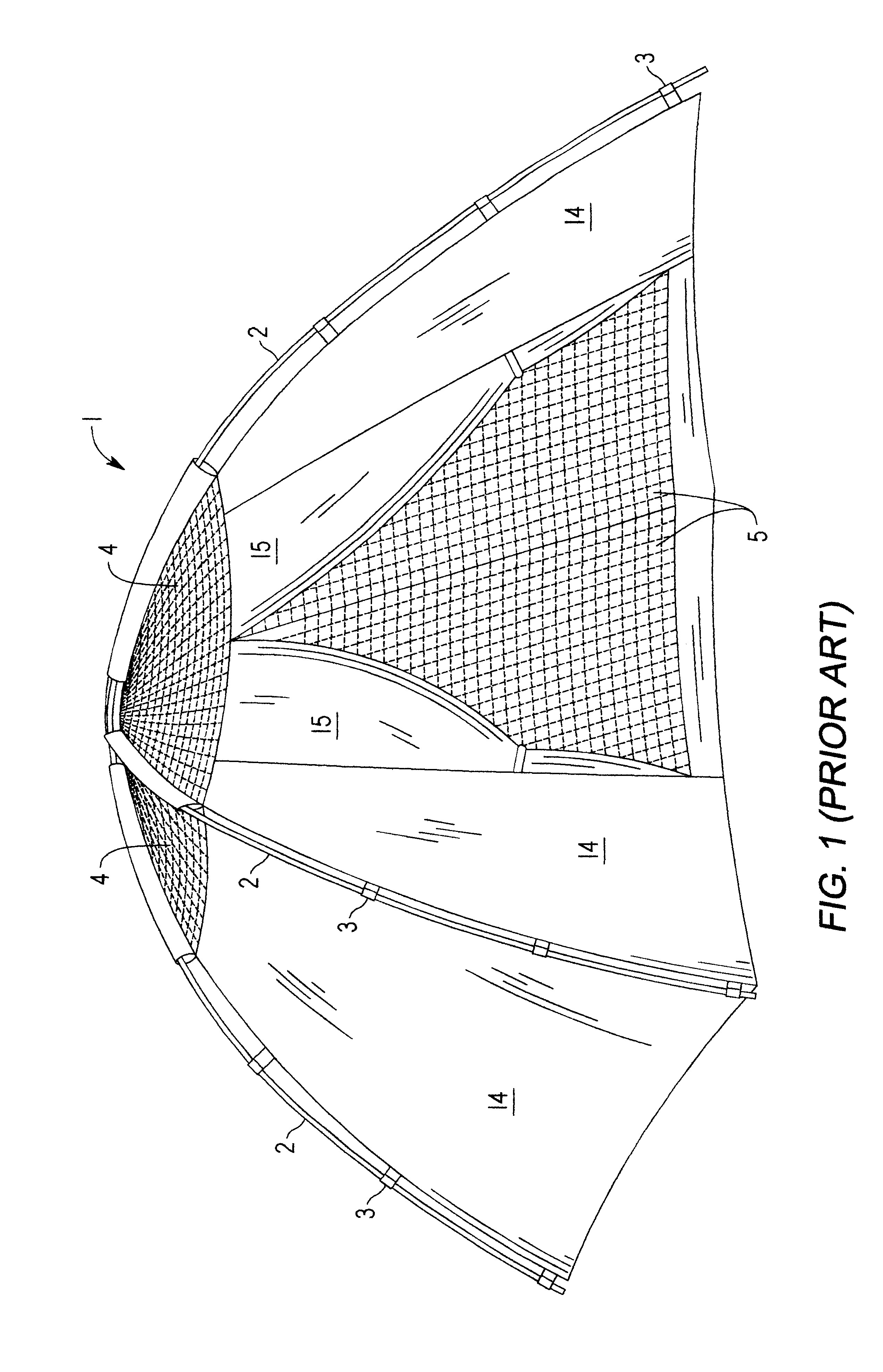
Additional embodiments are shown in FIG. 4. In this figure a detail drawing of the inner pole footing 10 is shown. A footing for the pole is needed to keep the interior pole 12 from damaging the tent. Extra tent material 20 is added in the t...


PUM


Abstract

An electric fan with mounted light (6) mounted overhead within a square dome camping tent (1). The fan/light unit is supported by a series of fiberglass poles (12), and pole footings (10). The fan/light unit is powered by a portable power supply and control unit (7) which contains power switches (23), an updraft/downdraft switch (24), an accessory plug (25), and a charger plug (27).

Description

Not Applicable.BACKGROUND--Field of InventionThis invention relates generally to electric fans, and more specifically, to a portable fan which is designed to be suspended overhead in a camping tent, with a compact portable power supply.BACKGROUND--Description of Prior ArtWhen camping, heat and humidity in tents are common problems. Portable battery operated fans are often used to move air in tents. However, the common portable fan moves little air in a tent and thus fails to cool the occupants. Also, to remove excess humidity from a tent inside air must be exchanged with outside air. Common portable fans fail to exchange enough air to remove excess humidity.There are other disadvantages of common portable fans for camping. Tent space is limited and cumbersome fans can take up precious room. A fan on a tent floor also needs to be free of obstacles in order to move sufficient air, again taking up more room. These fans can be easily knocked over rendering them useless. Also, common por...

Claims


Application Information

Patent Timeline
IPC IPC(8): E04H15/14E04H15/32E04H15/00
CPCE04H15/14E04H15/32Y10S135/91
Inventor JENNINGS, HARRY G.
Owner JENNINGS HARRY G
Why Eureka
Try Eureka