Grid Synchronisation

a synchroniser and grid technology, applied in the field of power generation, can solve the problems of huge losses in resistors, reduced system life and reliability, and ground faults on the grid

Active Publication Date: 2013-05-30
TESLA INC
View PDF14 Cites 122 Cited by
  • Summary
  • Abstract
  • Description
  • Claims
  • Application Information

AI Technical Summary

Benefits of technology

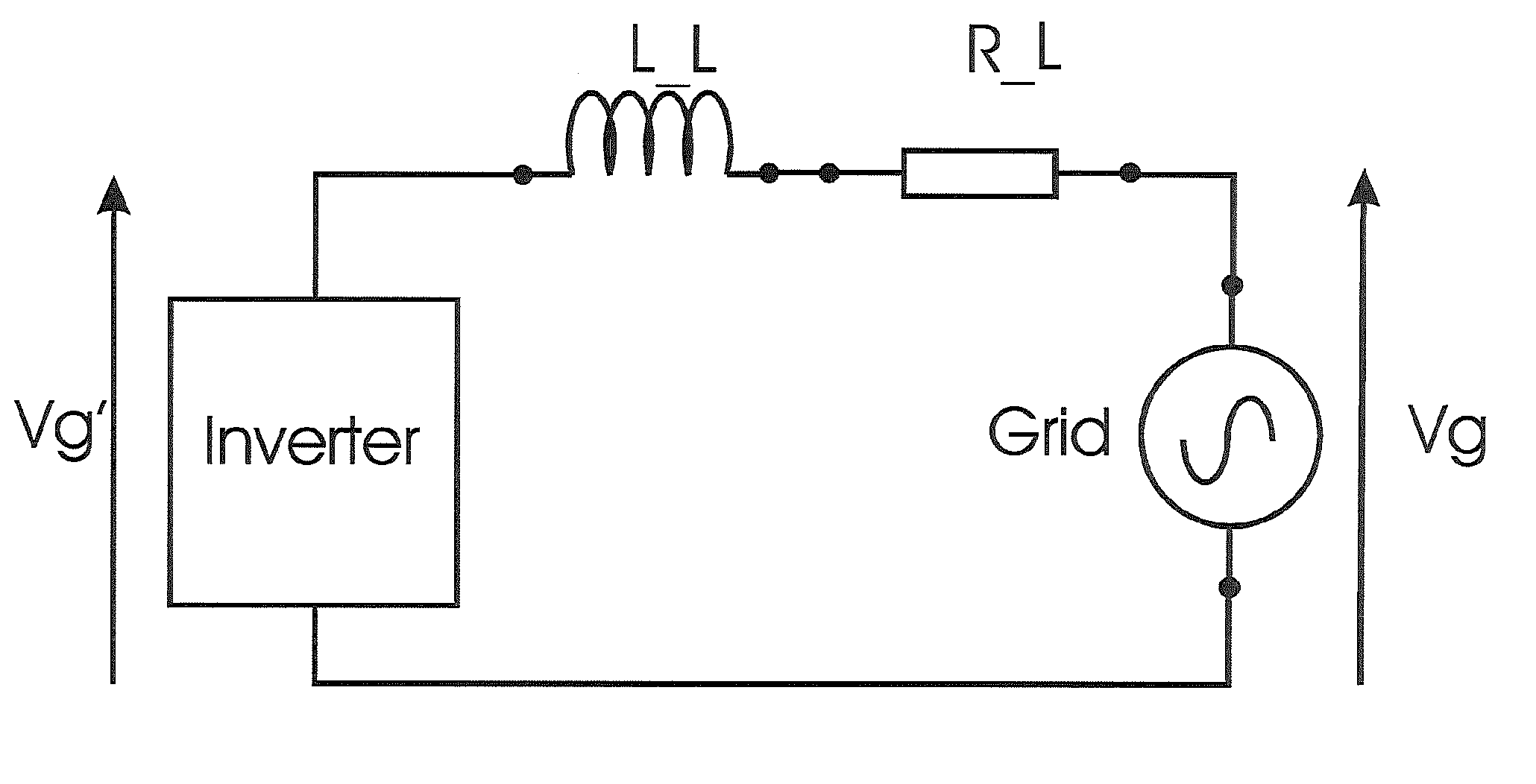
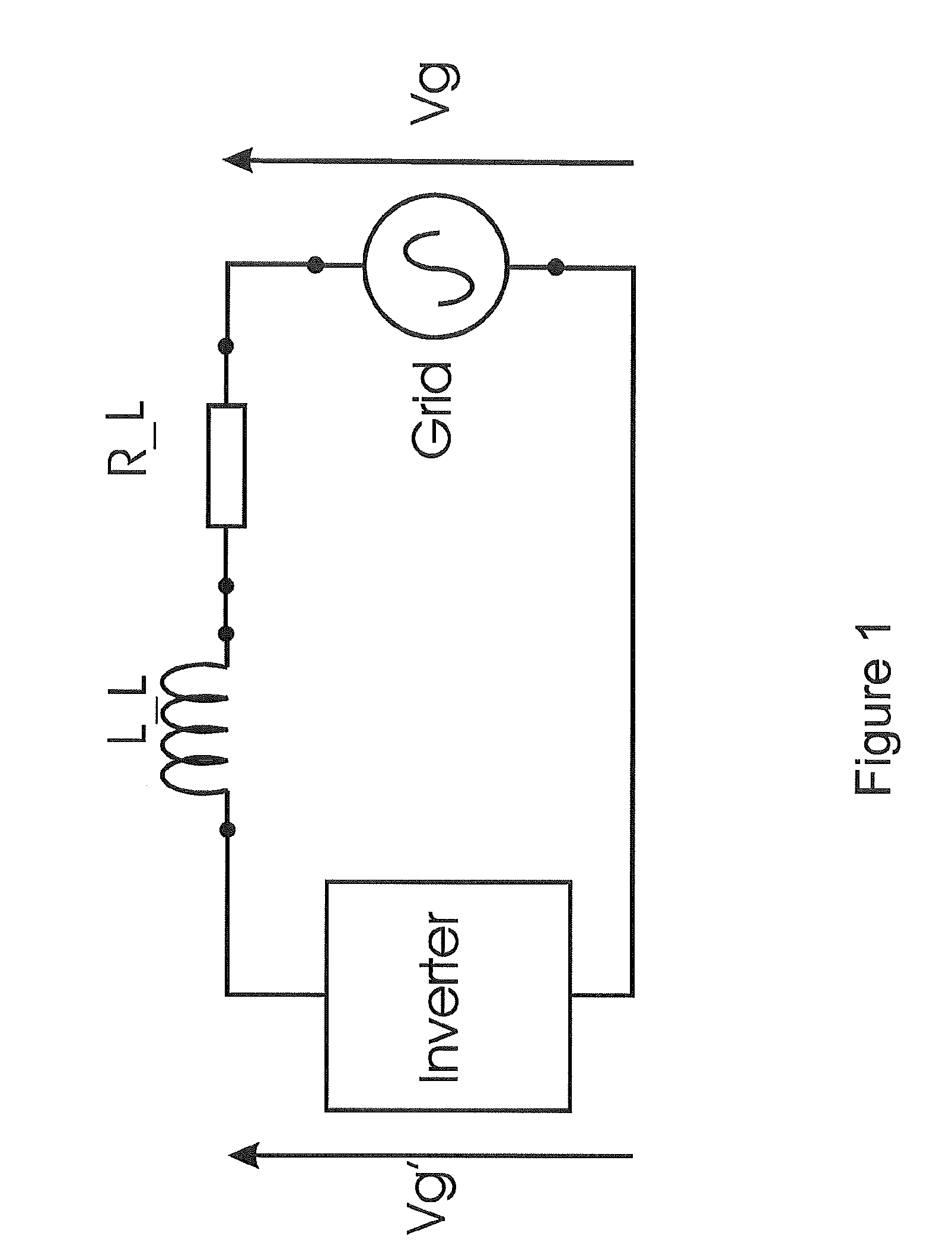
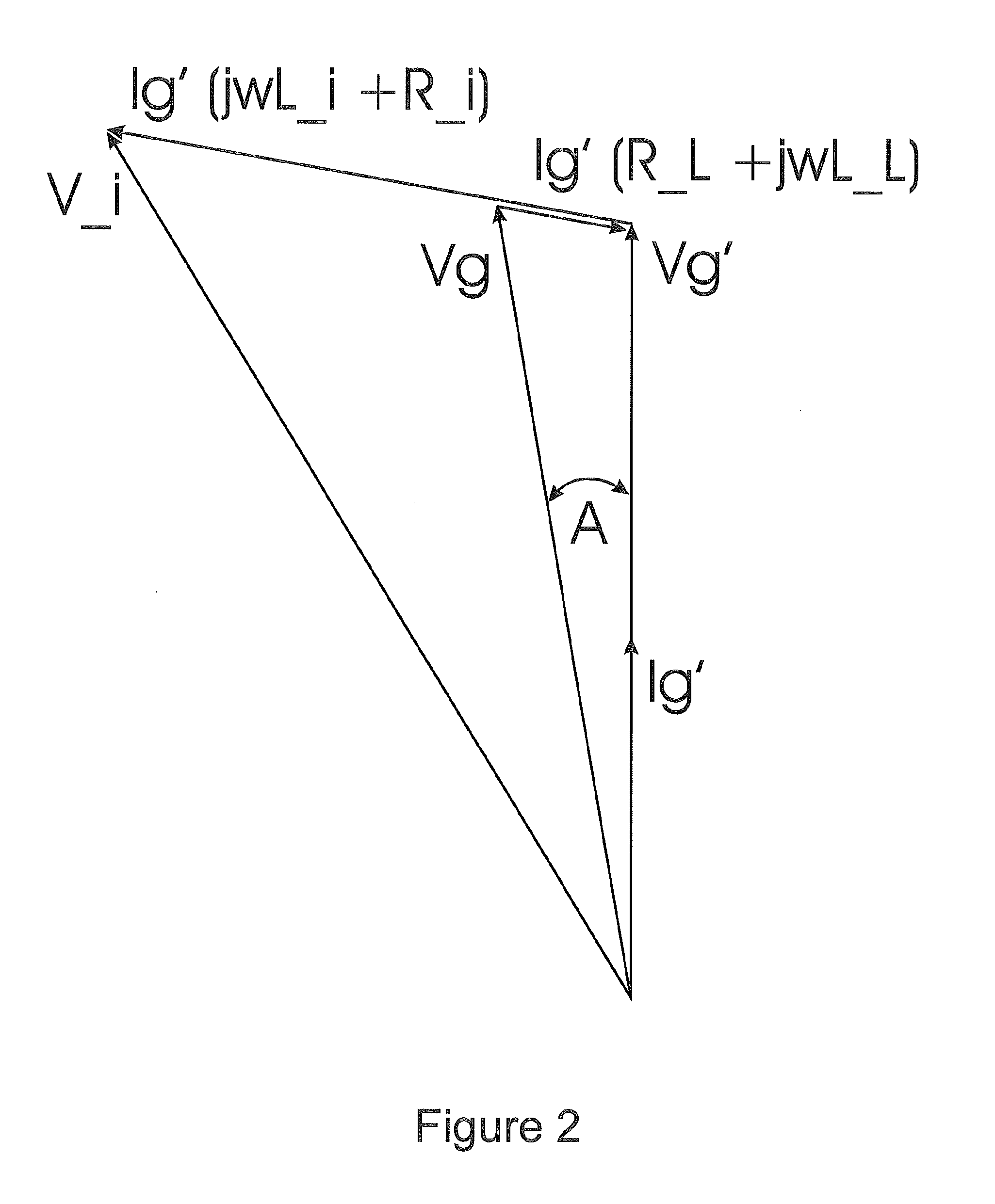
The patent is about controlling an inverter to synchronize with the AC grid mains, regardless of the load on the line. By sensing and transmitting the characteristics of the grid, the inverter can adjust its output to match the grid's. This results in a more efficient and reliable power system.

Problems solved by technology

One of the key problems is how to rapidly remove gate charge and at the same time minimise power loss in the driving circuit.
If charge is not removed rapidly from the gate terminal a shoot-through problem results and a ground fault develops on the grid.
However, the use of small ohmic resistors to form potential dividing circuit often results in huge losses in the resistors and therefore reduced lifetime and reliability for the system.

Method used


Image

  • Grid Synchronisation
  • Grid Synchronisation
  • Grid Synchronisation

Examples


application examples

[0074]The driver circuits can be used in applications where synchronised switching of the grid is used for power transfer in either direction. One example is as used in the circuit diagram of FIG. 13. The principle of operation of this circuit is described in our earlier patent application (ibid). In this circuit the drivers switches the two IGBTs in alternate half cycles to allow power transfer from a source such as solar photovoltaic energy.

[0075]FIG. 14 shows another application of the proposed driver circuit. In this case power can be transferred from the grid to the load or the load can supply power to the grid. FIG. 15 illustrates the waveforms appearing across the load. The amplitude difference between Vg and VL are for illustration clarity.


PUM


Abstract

The invention relates to a grid synchroniser for connecting an AC output of a power converter to the AC grid mains. In one aspect the invention provides a grid synchroniser comprising an inverter controller to control an AC output of the inverter, the controller including a receiver to receive grid data from a grid sensor location remote from said inverter. In another aspect we describe techniques for rapid removal of charge from a control terminal of a power switching device such as a MOSFET, IGBT or Thyristor using a particular driver circuit.

Description

FIELD OF THE INVENTION[0001]The invention relates to power generation, and in particular to a grid synchroniser for connecting an AC output of a power converter to the AC grid mains. The invention also relates to driver circuits, in particular for power semiconductor switching devices of the type that are employed in ac (alternating current) inverters. More particularly aspects of the invention relate to techniques for rapid removal of charge from a control terminal of a power switching device such as a MOSFET (Metal Oxide Semiconductor Field Effect Transistor) IGBT (Insulated Gate Bipolar Transistor) or Thyristor.BACKGROUND TO THE INVENTION[0002]Attempts have been made previously to directly couple switching semiconductor devices to the grid in order to maintain phase synchronisation and simplify system design. One of the key problems is how to rapidly remove gate charge and at the same time minimise power loss in the driving circuit. If charge is not removed rapidly from the gate ...

Claims


Application Information

Patent Timeline
Patent Type & Authority Applications(United States)
IPC IPC(8): H02J3/40
CPCH02J3/50H02J3/40H02J3/48H02J2300/24H02J3/381H02J3/46Y02E10/56H02J3/38H02J3/388
Inventor AMARATUNGA, GEHAN ANIL JOSEPHCHISENGA, LESLEYVIRAJ, ANDRABADU
Owner TESLA INC
Why Eureka
Try Eureka