Transmission cable structure for GHz frequency band signals and connector used for transmission of GHz frequency band signals

a technology of ghz frequency band and transmission cable, which is applied in the direction of logic circuit coupling/interface arrangement, pulse technique, waveguide, etc., can solve the problem of differential signal skew due to fluctuation of characteristics of transistors, and require double the number of transistors

Inactive Publication Date: 2006-09-26
THE FUJIKURA CABLE WORKS LTD
View PDF31 Cites 234 Cited by
  • Summary
  • Abstract
  • Description
  • Claims
  • Application Information

AI Technical Summary

Benefits of technology

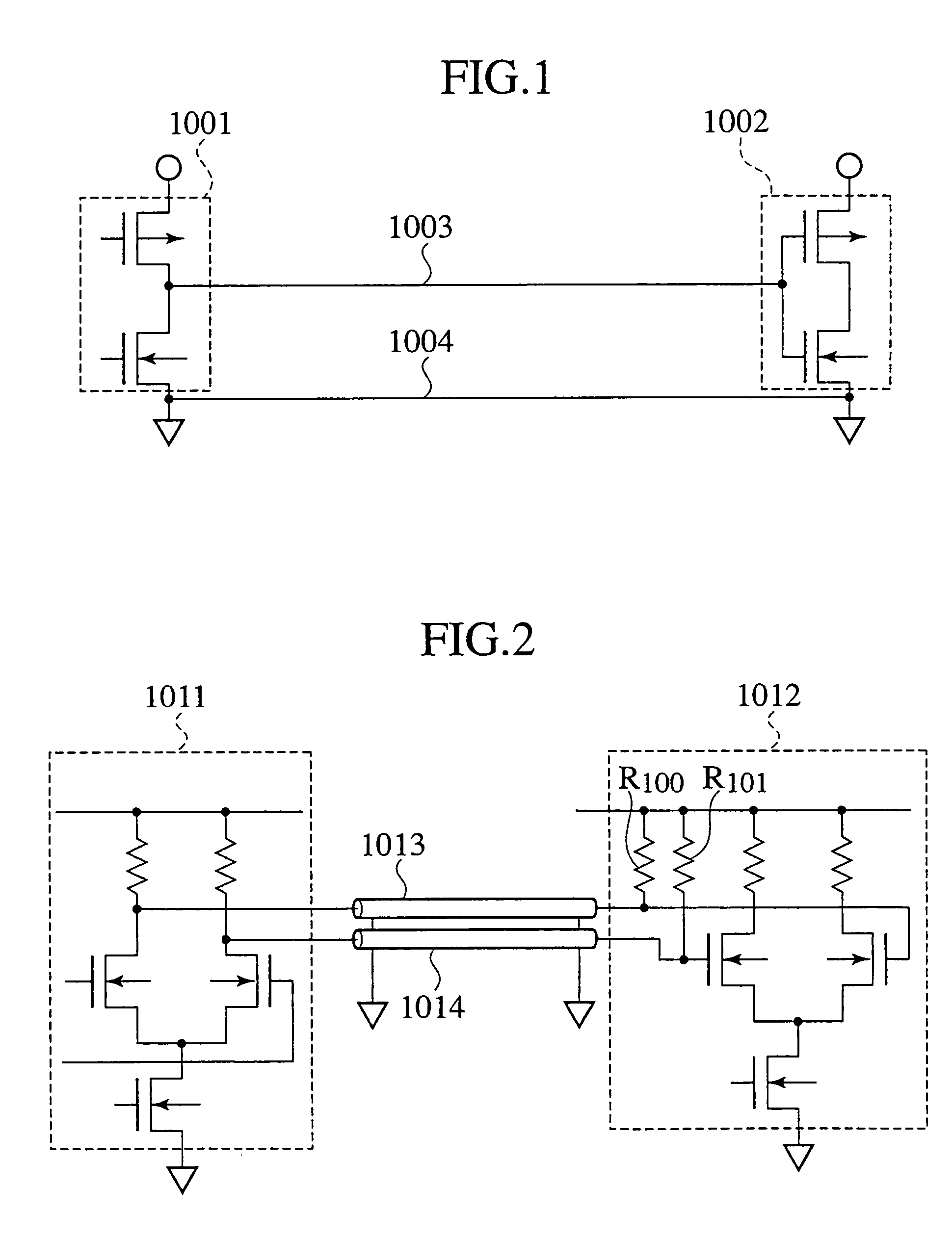
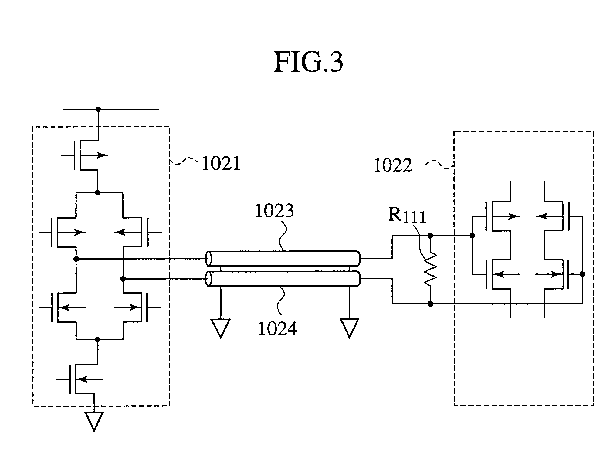
[0016]The transmission cables 1013 and 1014 shown in FIG. 2 or transmission cables 1023 and 1024 shown in FIG. 3 have a pair cable structure comprised of two cables, for suppressing leak of electromagnetic waves from the transmission cables to the outside. Moreover, these structures reference ground in order to achieve matching of standard voltage levels between functional circuit blocks. Thus, this lead to the issue that terminating resistance R 100 and R 101 or R 111 must be laid due to considerations of the coupling coefficients.
[0018]FIG. 4A shows the results of a simulation of electrical field strength distribution for pair cable 1031. The direction of the arrows shows the direction of the electrical field (electric flux lines), the size of the arrows indicating the strength of the electric field (the density of the electric flux line). The pair cable 1031 is formed of insulated conductors having a diameter of 0.5 mm, each being covered with insulating material having a relative permittivity of 1.96. The wires are arranged flat with a gap therebetween of 0.775 mm. The radius of a wire is half the distance of the gap. The characteristic impedance Z0 of the pair cable 1031 is 99.872 Ω. As seen from FIG. 4A, electric flux lines leak out substantially from the pair cable 1031 to the atmosphere. Accordingly, the coupling between wires comprising the pair cable weakens and thus the electric flux lines leaking out are apt to create cross talk in other pair cables. Further, FIG. 4C is a graph showing the results of simulation of the S-parameters for the four pair cables k12, k34, k56 and k78 of FIG. 4B. Here, S21, S41, S61, and S81 represent the respective S-parameters for pair cable k12 itself, and between pair cable k12 and k34, pair cable k12 and k56 and pair cable k12 and k78. Thus, it is evident that cross talk arises easily in flat cable 1032 inviting transmission loss.

Problems solved by technology

Thus, this lead to the issue that terminating resistance R 100 and R 101 or R 111 must be laid due to considerations of the coupling coefficients.
Another issue affecting conventional differential circuits are that skew due to fluctuation of characteristics of transistors is inherent in differential signals.
Therefore, in the on-off transition of switching substantial spike current occurs due to that skew, causing an issue known as the EMI problem.
Another issue affecting conventional differential circuits is that they require usage of double the number of transistors.
Accordingly, the coupling between wires comprising the pair cable weakens and thus the electric flux lines leaking out are apt to create cross talk in other pair cables.
Thus, it is evident that cross talk arises easily in flat cable 1032 inviting transmission loss.
However, for the 10G BASE-T, which is being investigated by the IEEE as a standard model of frequency band, exceeds 1 GHz, the existing CAT 6 cable carrying 250 MHz frequency band cannot be applied.
Further, RJ-45 is used for connectors, however, reflection of electromagnetic waves arises at mismatching points of impedance because the characteristic impedance of the connecter parts is not uniform, causing a worsening of the S / N ratio and decreasing the frequency band of the transmitted signal.

Method used


Image

  • Transmission cable structure for GHz frequency band signals and connector used for transmission of GHz frequency band signals
  • Transmission cable structure for GHz frequency band signals and connector used for transmission of GHz frequency band signals
  • Transmission cable structure for GHz frequency band signals and connector used for transmission of GHz frequency band signals

Examples


Embodiment Construction

[0079]The preferred embodiments according to the present invention will now be described with reference to the drawings.

[0080]

[0081]When theoretically studying transmission cables, whether to form a model using concentrated constant circuits or distributed constant circuits depends on the relationship of the length L of a transmission cable and the wavelength λ of the transmission signal transmitted in the cable. For the present invention the critical value for the length of a transmission cable is obtained from

[0082]Lcritical=λ40=c040⁢⁢fclock⁢μr⁢ɛr,(1)

where λ represents the wavelength of a fundamental harmonic wave (sine wave) where Fourier series expansion is applied to a transmission signal (pulse signal) having a pulse waveform, C0 is the speed of the electromagnetic wave in a vacuum, μr the relative permittivity of insulating material encompassing the transmission cable, and fclock represents the frequency of maximum clock pulse flowing in the transmission cable.

[0083]The meani...


PUM


Abstract

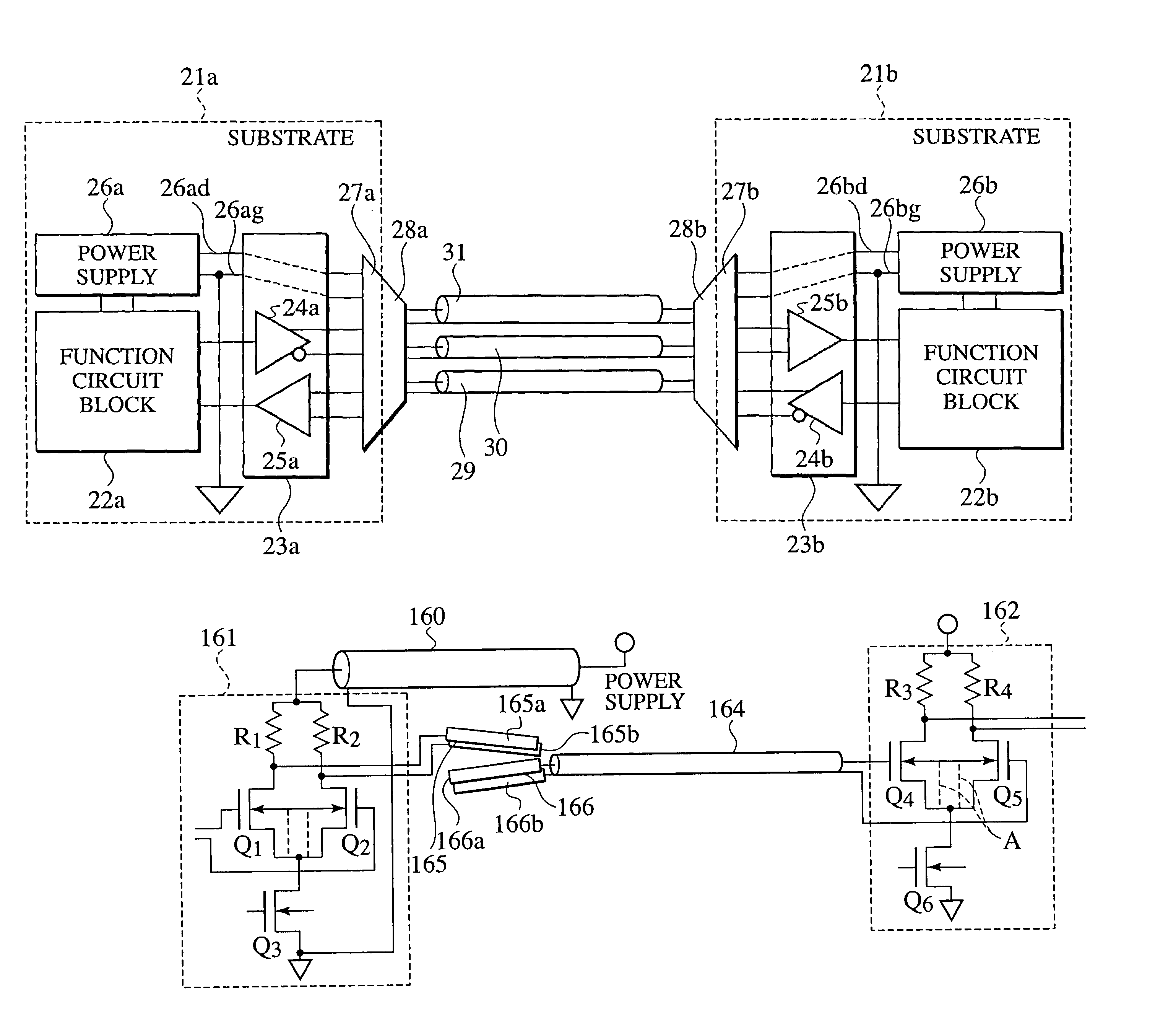
A differential signal transmission cable structure for transmitting differential signals having GHz frequency band in the present invention is provided with a differential signal transmission pair cable 30 connecting a driver circuit 23a and a receiver circuit 23b, for transmitting differential signals having GHz frequency band, and a power supply ground transmission pair cable 31 connecting ground and a first power supply 26a connected to the driver circuit and ground and a second power supply 26b connected to the receiver circuit. Further characteristic impedance of the differential signal transmission pair cable is matched to that of the driver circuit and the receiver circuit, thereby enabling TEM waves of differential signals having GHz frequency band transmission mode to be maintained when the differential signals are transmitted.

Description

[0001]This application is based on and claims priority under 35 U.S.C. §119 with respect to Japanese Patent Application No. 2003-137854 filed on May 15, 2003 and Japanese Patent Application No. 2003-196062 filed on Jul. 11, 2003, the entire content of which is incorporated herein by reference.BACKGROUND OF THE INVENTION[0002]The present invention relates to a transmission cable structure for transmission of GHz frequency band signals and a connector used for transmission of GHz frequency band signals and more specifically to a connector used for transmission of GHz frequency band signals and a transmission cable structure for transmission of GHz frequency band signals that enables TEM waves to be transmitted between functional circuit blocks without attenuation.[0003]Recently, a variety of problems have arisen concerning long distance communications between functional circuit blocks in line with demands for high-speed communications, such that high-speed communications of 10 Gbps or...

Claims


Application Information

Patent Timeline
Patent Type & Authority Patents(United States)
IPC IPC(8): H03K19/0175H01P1/04H03K19/00H01P3/02
CPCH01P3/02H01L2224/45565H01L2224/48137H01L2224/49175H01L2924/30107H01L2924/3011H01L2924/13091H01L2924/00H01L24/45H01L2224/45028H01L2224/45144H01L2224/45147H01L2924/00014H01L2224/45015H01L2924/30111
Inventor OTSUKA, KANJIUSAMI, TAMOTSUUEDA, CHIHIROAKIYAMA, YUTAKAKOYASU, OSAMU
Owner THE FUJIKURA CABLE WORKS LTD
Why Eureka
Try Eureka