High efficiency modulated power supply

a power supply and high efficiency technology, applied in the field of modulated power supplies, can solve the problems of generating heat which must be dissipated, relative high resistive loss, power loss of resistive loss, etc., and achieve the effects of linearity, cost and reliability, and modulator siz

Inactive Publication Date: 2008-07-01
APPLE INC
View PDF3 Cites 115 Cited by
  • Summary
  • Abstract
  • Description
  • Claims
  • Application Information

AI Technical Summary

Benefits of technology

The power supply described in this patent can be used in a variety of applications, including wireless communication base stations. It is designed to amplify signals with a wide bandwidth, which is particularly important for third generation UMTS base stations. The power supply tracks the envelope of the input signal, which helps to reduce power costs and improve overall efficiency, linearity, modulator size, cost, and reliability. The invention can also benefit applications that require modulation of voltage or current with a significant DC component in the signal.

Problems solved by technology

The technical problem addressed in this patent is to improve the performance of modulated power supplies, particularly in applications where the modulating signal has a wide bandwidth, by reducing power losses and heat generation caused by high resistive loss in small, fast switching devices.

Method used


Image

  • High efficiency modulated power supply
  • High efficiency modulated power supply
  • High efficiency modulated power supply

Examples


Embodiment Construction

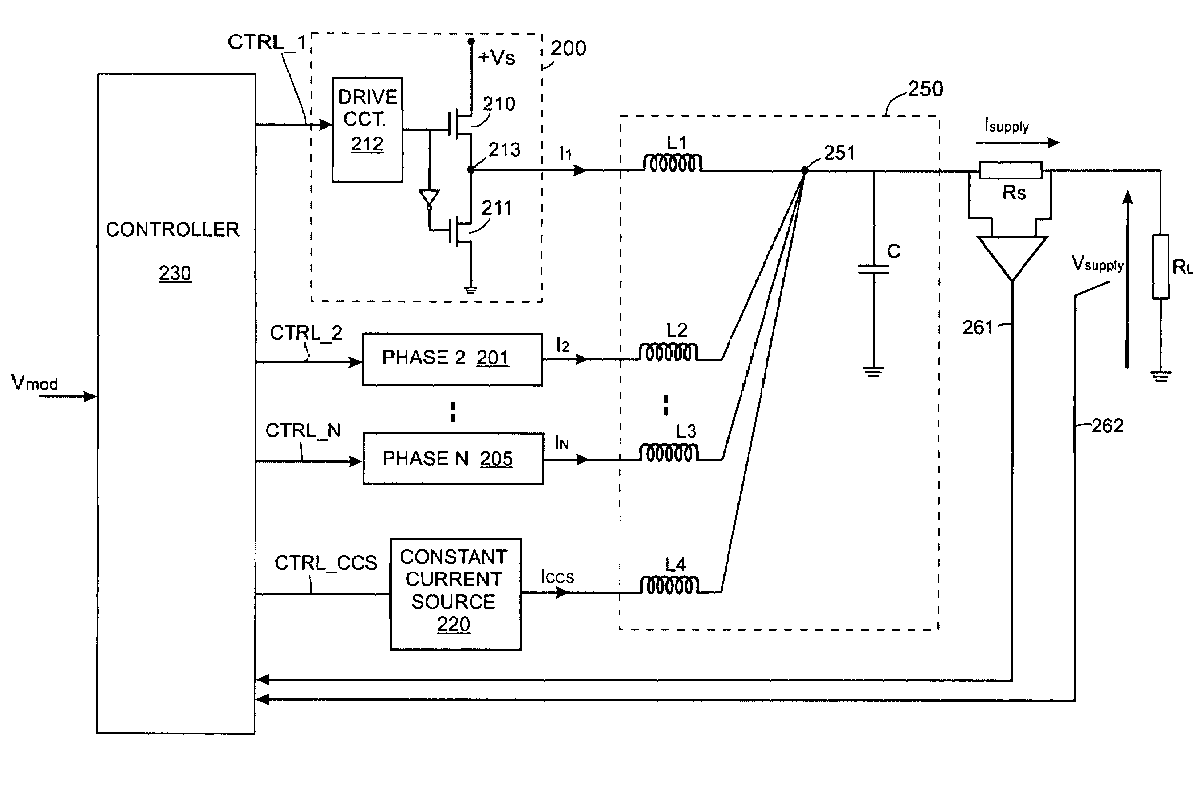
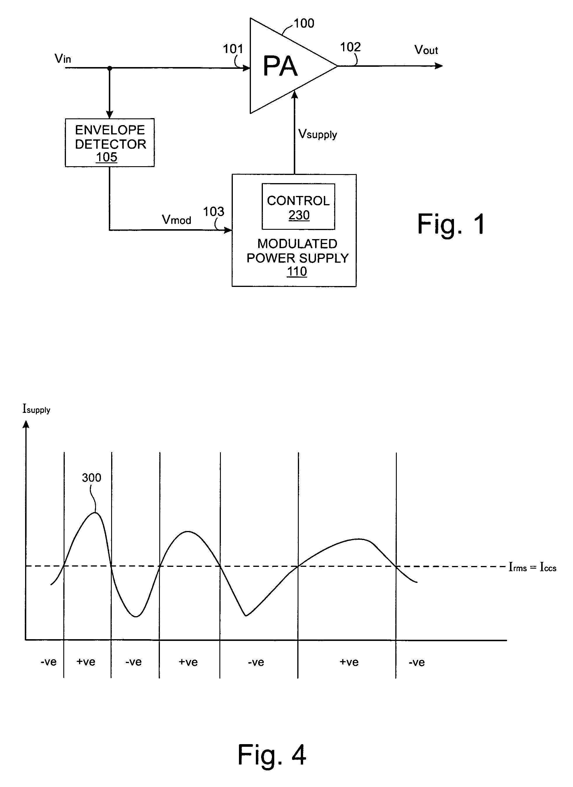
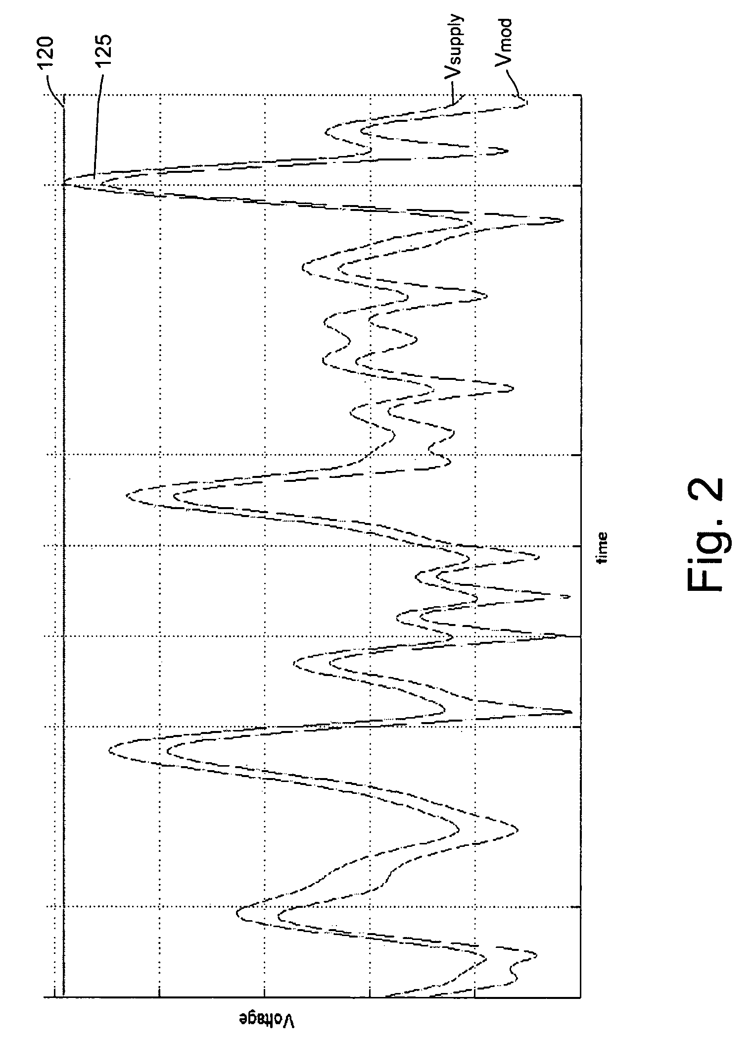
[0026]Before describing the invention in detail, FIGS. 1 and 2 illustrate an application of the invention in order to put the invention into context. FIG. 1 shows a power amplifier arrangement comprising a power amplifier 100 and a modulated power supply 110. An input signal Vin, which is to be amplified by the power amplifier 100, is also applied to an envelope detector 105. A signal, Vmod, representing the envelope of the input signal is applied to an input 103 of the modulating power supply 110. A control circuit 230 within the modulating power supply 110 receives the signal Vmod and determines appropriate control signals which cause the power supply 110 to generate a supply voltage Vsupply which substantially tracks Vmod. An amplified output signal Vout is taken from an output 102 of the power amplifier 100. FIG. 2 shows the operation of the power supply over a period of time, showing the envelope of the input signal Vmod and the envelope of the dynamically modulated power suppl...


PUM


Abstract

A modulated power supply comprises a power switching stage having at least one power switching device for generating a power signal in response to an input modulating signal. A current source is positioned in parallel with the power switching stage and continuously generates an output current. An output stage combines the power signal and the output current to form an output power supply signal. The current source supplies some, or all, of the required current at any given time. The switching device in the power switching stage either supplies the remaining required current or sinks any excess current. This has an advantage of reducing the average and peak currents flowing through the switching device, and hence the average power dissipation in the device. The output current can be set at an average (e.g. RMS) value of the current in the output power supply signal.

Description


Claims


Application Information

Patent Timeline
Owner APPLE INC
Why Eureka
Try Eureka