
In-line roller skates having quick-release axle system with safety retaining pin mechanism

a technology of safety retaining pin and roller skate, which is applied in the direction of skates, skate parts, skateboards, etc., can solve the problems of difficult, if not impossible, to remove the axle with the standard designated tools, and the installation or removal of the wheels is a tedious and time-consuming process, so as to avoid the shortcomings and drawbacks

Inactive Publication Date: 2003-08-19
AGE OF BLADES
View PDF16 Cites 11 Cited by
  • Summary
  • Abstract
  • Description
  • Claims
  • Application Information

AI Technical Summary

Benefits of technology

The system enables rapid wheel installation and removal without tools, preventing stripping and crossthreading, ensuring a secure fit and easy maintenance, accommodating various axle aperture diameters and bearing spacers.

Problems solved by technology

All of these method involve a tightening sequence using allen wrenches, screw drivers, or wrenches of some type making installation or removal of the wheels a tedious and time-consuming process.
In addition, it is a common problem to have the keyed slot, whether it be for an allen key or screwdriver, strip out making it extremely difficult, if not impossible, to remove the axle with the standard designated tools.
Usually these can only be removed by drilling or cutting the axle and replacing it with a new one.
It is also possible for crossthreading to occur during assembly which makes removal extremely difficult as well.

Method used


Image

  • In-line roller skates having quick-release axle system with safety retaining pin mechanism
  • In-line roller skates having quick-release axle system with safety retaining pin mechanism
  • In-line roller skates having quick-release axle system with safety retaining pin mechanism

Examples


first embodiment

A second illustrative embodiment of the quick-release axle system of the present invention is shown in FIGS. 8 and 8A. While this embodiment is quite similar to the embodiment of FIG. 3, there are a number of minor differences. In particular, the bearing spacer 30 in FIG. 8 does not have an outer bore surface that slides into the inner bore of the inner race of the bearing, as in the first embodiment shown in FIG. 3. Instead, the bearing spacer 30 is shaped like a bushing whose inner and outer diameters are exactly the same as the inner and outer diameters of the inner race of the bearing itself. Therefore, the axle shaft diameter is larger in order to correspond with the diameter of the inner bore of the inner bearing race.

Circumferential grooves 31A and 31B are cut into the inner surface of the inner bore of the bearing spacer 30 (about 0.030 inches deep) in lieu of the equally spaced holes in the bearing spacer of the first illustrative embodiment described above. When the axle s...

second embodiment

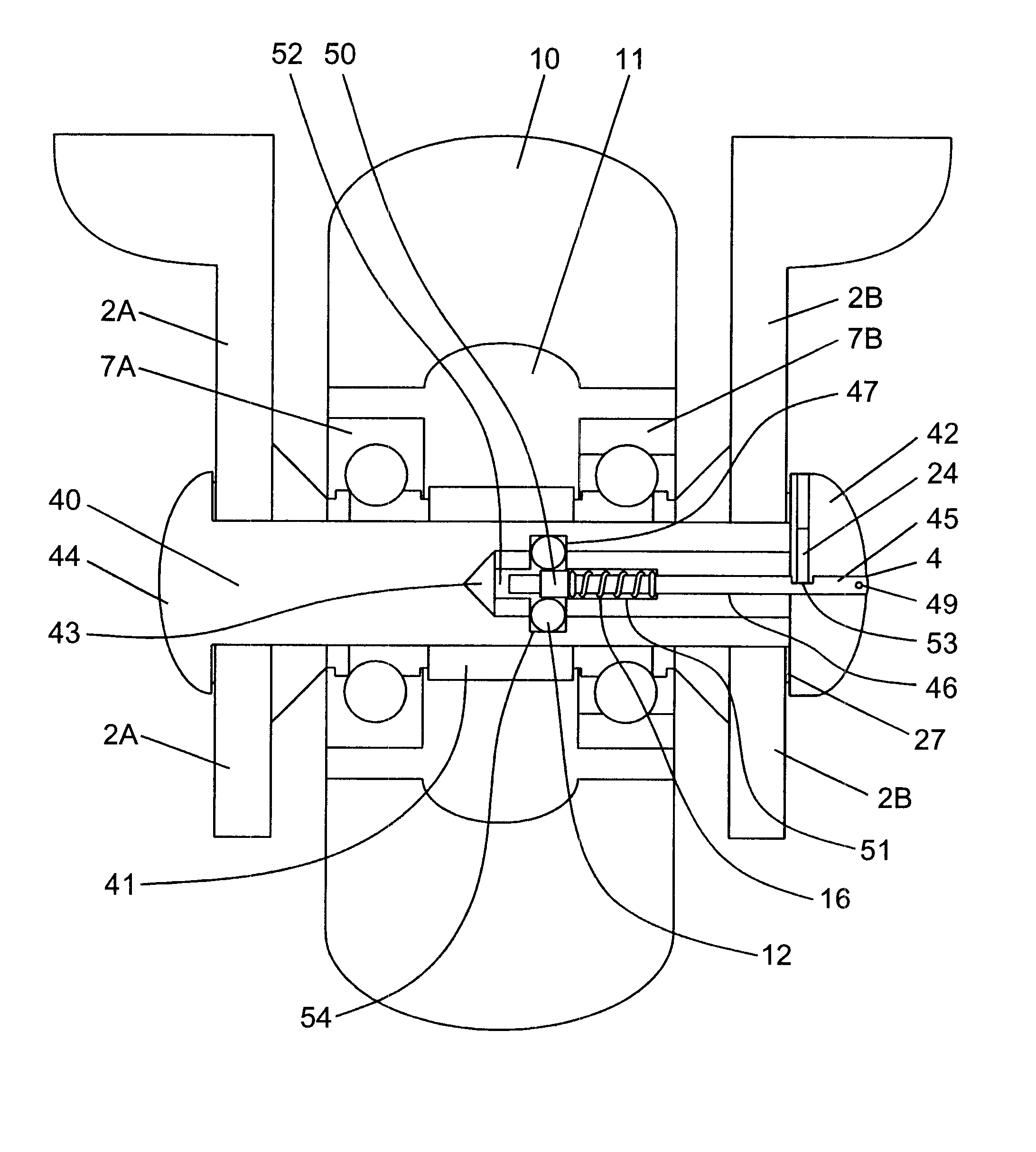
In FIG. 9, a third alternative embodiment of the present invention is shown. In this embodiment, the bearing spacer is not used as part of the axle-shaft locking mechanism. Instead, the axle system comprises: a main axle shaft 40 insertable through the first skate frame wall 2A, the first bearing 7A, the bearing spacer 41, the second bearing 7B, and the second skate frame wall; and a secondary axle shaft 42 for insertion within a central bore 43 formed within the main axle shaft 40. As shown in FIG. 8, the main shaft axle has head portion 44 formed on one end of its cylindrical body portion, and central bore 43 formed through the end of its body portion opposite head portion 44. The length of the bore 43 extends about half way across the length of the axle shaft. A release pin 45, similar in design as the release pin 9A (9B) shown in FIG. 8, is provided for insertion through a central bore 46 formed in the secondary axle shaft 42, to engage with ball bearing 12. As shown in FIG. 9, ...


PUM


Abstract

A quick-release type axle system for in-line skates. A pair of axle shafts cooperate with each other to support a wheel between a pair of frames. A release pin is inserted into a central bore formed through the axle shafts to lock the axle shafts relative to each other. In one embodiment, the release pin is pulled outwardly to release the axle shafts from the locked configuration, whereas in another embodiment, the release pin is pushed inwardly to achieve unlocking of the axle shafts. In some embodiments, a pair of release pins are used to achieve the quick-release mechanism of the present invention.

Description

BACKGROUND OF INVENTION1. Field of InventionThe present invention relates generally to in-line roller skates, and more particularly to a quick-release axle system for use in the same.2. Brief Description of Prior ArtThere are currently a wide variety of prior art axle systems in use for mounting the wheels on in-line roller skates. Each skate manufacturing company has it's own unique design and there are several after-market companies which also manufacture axle kits. Although each one differs somewhat in design, the general configuration invariably involves a threaded portion which is fastened with a nut.In the common nut and bolt type axle system, the bolt (acting as the axle shaft) passes through the axle aperture in the skate frame, then through the bearings and bearing spacer, and is held in place with a nut which is threaded onto the bolt from the opposite side and tightened against the skate frame.Other systems have the threaded portion on the inside of the axle shaft. A scre...

Claims


Application Information

Patent Timeline
Patent Type & Authority Patents(United States)
IPC IPC(8): A63C17/00A63C17/22
CPCA63C17/22A63C17/226
Inventor SZENDEL, ADRIAN JAMES
Owner AGE OF BLADES
Learn More