Actively controlled regenerative snubber for unipolar brushless DC motors

a dc motor and active control technology, applied in the direction of electronic commutators, dynamo-electric converter control, instruments, etc., can solve the problems of affecting the efficiency of the motor, excessive amount of energy converted into heat, and discharging of stored energy in the form of hea

Inactive Publication Date: 2003-10-07
SIEMENS VDO AUTOMOTIVE INC
View PDF10 Cites 36 Cited by
  • Summary
  • Abstract
  • Description
  • Claims
  • Application Information

AI Technical Summary

Problems solved by technology

The disadvantage of the RCD snubber is the dissipation of stored energy in the form of heat.
If the switching frequency of the device to which the snubber is attached is high, the amount of energy converted to heat may be excessive.
When using the RCD snubber in the control circuit of a unipolar brushless DC motor, there arise some unique challenges particularly where low voltage, high current applications are concerned.
Consequently, the efficiency of the motor is adversely affected at high motor speeds.
For a 600 watt (W) application,there would be an increase in losses and, therefore, the, snubber circuit would dissipate more power.
The additional reverse protection devices have a voltage drop associated with them, causing a loss in motor efficiency.
The disadvantage of this method is the size of the transformers needed to return the energy stored in the snubber capacitor back to the positive voltage supply.
There is a cost penalty associated with the manufacture of bifilar windings (two windings per phase), however, in addition to the difficulty in winding them.

Method used


Image

  • Actively controlled regenerative snubber for unipolar brushless DC motors
  • Actively controlled regenerative snubber for unipolar brushless DC motors
  • Actively controlled regenerative snubber for unipolar brushless DC motors

Examples


Embodiment Construction

DURING TURN ON OF S.sub.1 (MODE I)

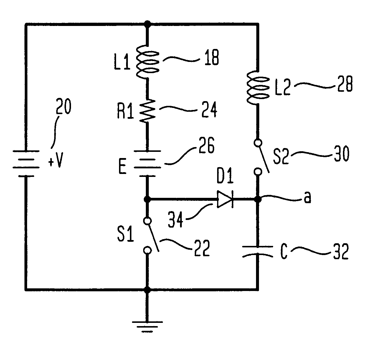
Referring to FIG. 7, the cycle is initially started with switch S.sub.1 being closed to energize the motor phase coil. If we assume that the motor phase coil has been conducting for some period of time at the onset of analysis, the phase coil will have a current flowing through it. The snubber capacitor will be precharged to a known voltage. The applied voltage is equal to the supply voltage V minus the back EMF voltage, E.

Our assumptions thus are:

V.sub.c (0.sup.+)=V.sub.o

i.sub.L1 (0+)=I.sub.o =i.sub.i (0.sup.+)

V=+V-E

By Kirchoff's Voltage Law (KVL): ##EQU2##

Therefore ##EQU3##

Since 1n a-1n b=1n a / b ##EQU4##

DURING TURN OFF OF S. (MODE II)

Referring to FIG. 8, Mode I ends when S.sub.1 is opened. At this point in time, the phase coil is carrying an initial current I.sub.o '. The phase coil will discharge into the snubber capacitor C through snubber diode D.sub.1. The voltage in the snubber capacitor will start to rise. To minimize high frequency harmonic...


PUM


Abstract

An actively controlled regenerative snubber configuration for use in unipolar brushless direct current motors comprises a first inductor, a first switch and a capacitor, all of which are connected in series to a positive voltage supply and in parallel with a second inductor and a second switch. The regenerative snubber is used to maintain constant voltage across the switches to prevent braking of the motor through conduction of motor back EMF and to return excess energy stored in the motor phase coils to the positive voltage supply. The return of energy to the positive rail is done in a manner so as to minimize conducted electromagnetic interference at the power leads.

Description

1. Field of the InventionThis invention relates to the field of devices for the protection of power electronic devices from extreme voltage or current changes and, in particular, to snubbers which protect switching devices in unipolar brushless DC motors and also return energy stored in such snubbers to the motors protected.2. Description of the Related ArtThe use of turn on and turn off snubbers for the protection of power electronic devices is not new. Snubbers in general are devices which limit overvoltage or overcurrent transients over electronic switching devices during or after the action of switching current. Snubbers have been used to protect devices against rapid changes in voltage with respect to time (dv / dt), rapid changes in current with respect to time (di / dt) and transient voltages.Although dissipative snubbers are very common, regenerative snubbers have been proposed to return energy stored in snubber elements back to the positive voltage supply, thereby increasing sy...

Claims


Application Information

Patent Timeline
Patent Type & Authority Patents(United States)
IPC IPC(8): H02P6/00H02M3/04H02M3/155H02M1/34
CPCH02M1/34H02M3/155H02P6/001Y02B70/1491H02M2001/342H02P6/34Y02B70/10H02M1/342
Inventor MAKARAN, JOHN EDWARD
Owner SIEMENS VDO AUTOMOTIVE INC
Why Eureka
Try Eureka