Methods and systems for reducing conducted electromagnetic interference

a technology of conducted electromagnetic interference and methods, applied in the direction of motor/generator/converter stopper, dynamo-electric converter control, electronic commutator, etc., can solve the problems of undesirable emi, adversely affecting other electronic circuit components, electric noise, etc., and achieve the effect of reducing conducted electromagnetic interferen

Inactive Publication Date: 2014-03-13
REGAL BELOIT AMERICA
View PDF10 Cites 5 Cited by
  • Summary
  • Abstract
  • Description
  • Claims
  • Application Information

AI Technical Summary

Problems solved by technology

Such electrical noise can adversely affect other electronic circuit components either within the electronic device itself or in nearby external electronic devices.
In connection with electric power supplies, EMI is undesirable because, for example, it can disturb the operation or degrade the performance of other equipment connected to the same source of power.
However, as a demand for smaller, more compact electric motors increases, manufacturers are limited in EMI filter design, size, and cost.

Method used


Image

  • Methods and systems for reducing conducted electromagnetic interference
  • Methods and systems for reducing conducted electromagnetic interference
  • Methods and systems for reducing conducted electromagnetic interference

Examples


Embodiment Construction

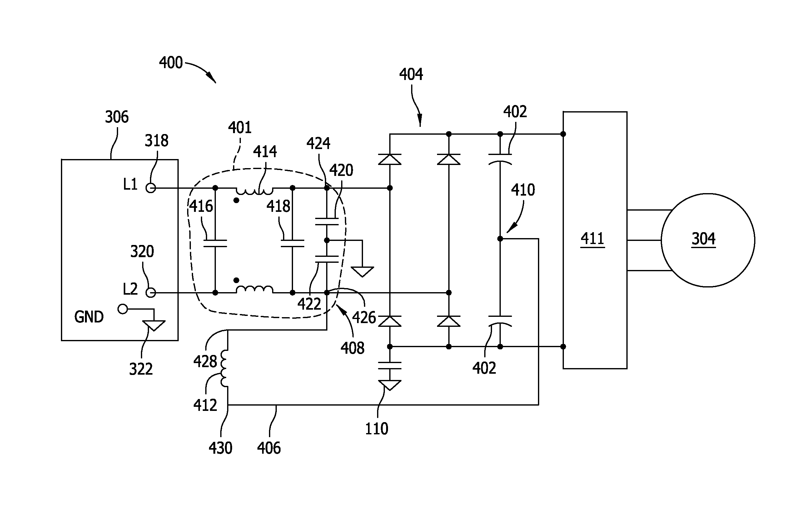
[0012]The methods and systems described herein facilitate reducing conducted electromagnetic interference (EMI) in a motor drive controller. EMI is reduced by positioning a power factor correction choke after an EMI filter and in line with a voltage doubling jumper wire.

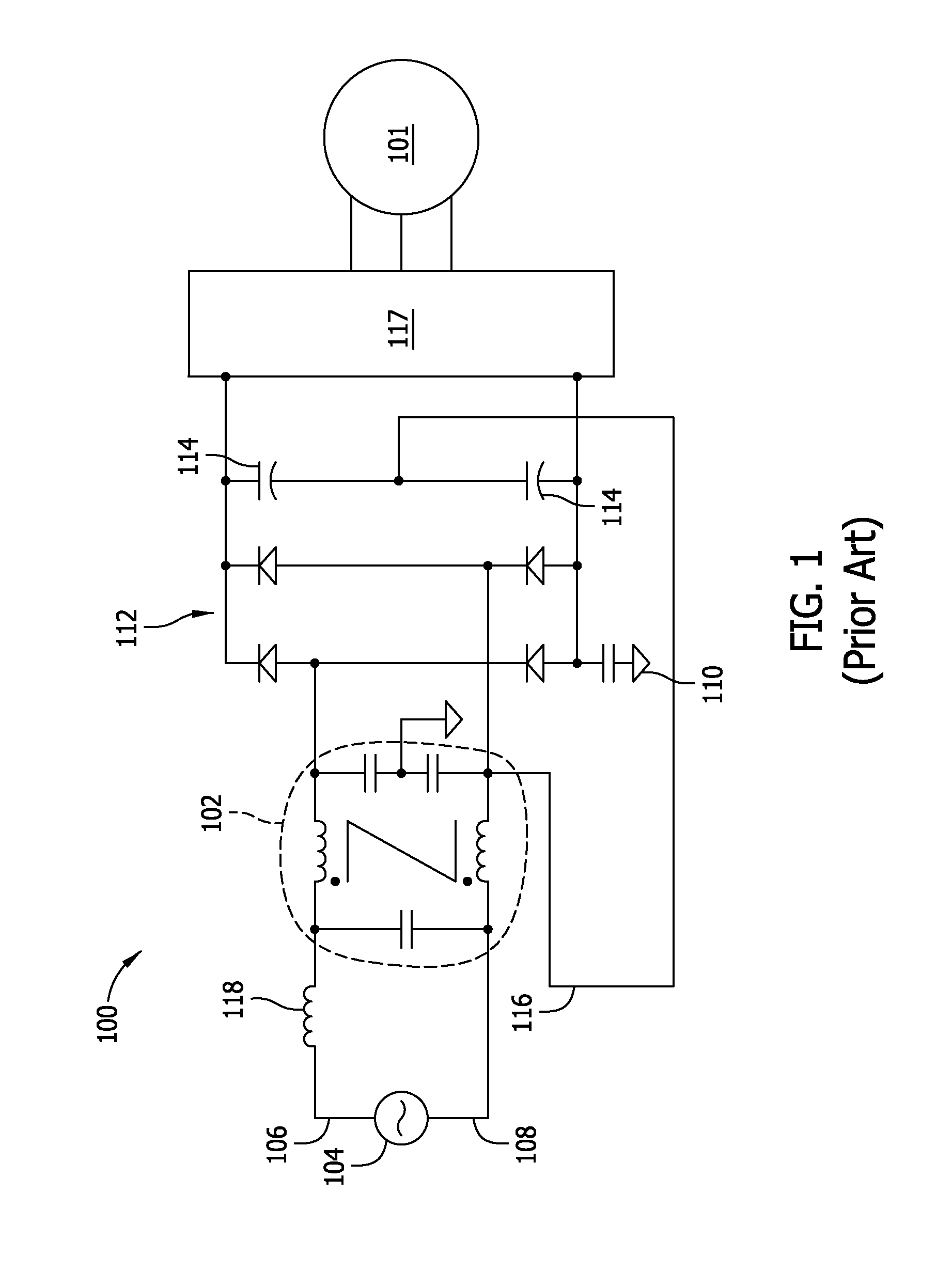
[0013]FIG. 1 is a circuit diagram of a known motor controller 100 for an electric motor 101 that includes an EMI filter 102. Motor controller 100 is coupled to a power supply 104, which is a single phase alternating current (AC) power supply that inputs AC power to a line conductor 106 and a neutral conductor 108 of electric motor 101. Power supply 104 is also coupled to earth ground 110. Power supply 104 may produce either 120 volts (V) RMS or 240 VRMS depending on the requirements of electric motor 101.

[0014]Motor controller 100 further includes a rectifier 112 for rectifying or converting the AC power from power supply 104 to a direct current (DC) power usable to control the motor. At least some modern 240 V elect...


PUM


Abstract

A drive circuit is provided for reducing conducted electromagnetic interference provided by a power line to a motor controller. The power line includes a first alternating current (AC) line output and a second AC line output. The drive circuit includes an EMI filter having a first input terminal, a second input terminal, a first output terminal, and a second output terminal. The first input terminal is configured to be coupled to the first AC line output and the second input terminal is configured to be coupled to the second AC line output. The drive circuit further includes at least two series-coupled filter capacitors positioned after the EMI filter and a power factor correction (PFC) choke. The PFC choke is coupled at a first end to the second output terminal and at a second end between the series-coupled filter capacitors.

Description

BACKGROUND OF THE DISCLOSURE[0001]The embodiments described herein relate generally to electric motors, and more specifically, to reducing conducted electromagnetic interference (EMI) in electric motors.[0002]At least some known electronic devices include electrical lines that produce unwanted electrical noise. Such electrical noise can adversely affect other electronic circuit components either within the electronic device itself or in nearby external electronic devices. Conducted EMI is an electrical noise current which is typically present in the radio-wave frequency range. This current originates from within a system of electrical devices rather than from an outside source such as a radio signal transmitter. Electric power supplies of electric motors are known to be significant generators of EMI. In connection with electric power supplies, EMI is undesirable because, for example, it can disturb the operation or degrade the performance of other equipment connected to the same sou...

Claims


Application Information

Patent Timeline
Patent Type & Authority Applications(United States)
IPC IPC(8): H02P6/00
CPCH02M1/126H02M1/4266H02P2201/15H02P29/50Y02B70/10H02P6/14
Inventor BECERRA, ROGER CARLOSDA, YAO
Owner REGAL BELOIT AMERICA
Why Eureka
Try Eureka