Electromagnetic interference monitoring and positioning method

A technology of electromagnetic interference and positioning method, which is applied in the direction of electromagnetic field characteristics, measuring interference from external sources, measuring electricity, etc., and can solve problems such as interference of components and subsystems, and system failure

Inactive Publication Date: 2020-09-04
XIDIAN UNIV
View PDF3 Cites 5 Cited by
  • Summary
  • Abstract
  • Description
  • Claims
  • Application Information

AI Technical Summary

Problems solved by technology

[0002] As the design of electronic systems becomes more and more complex, each component and subsystem has been well designed for electromagnetic interference emission during the development process, but in the process of system integration and debugging, some components and subsystems are often interfered, resulting in the failure of the entire system normal
Due to the limitation of the site and other factors during the system integration process, it is impossible to carry out relevant work inside the darkroom

Method used


Image

  • Electromagnetic interference monitoring and positioning method
  • Electromagnetic interference monitoring and positioning method
  • Electromagnetic interference monitoring and positioning method

Examples


Embodiment Construction

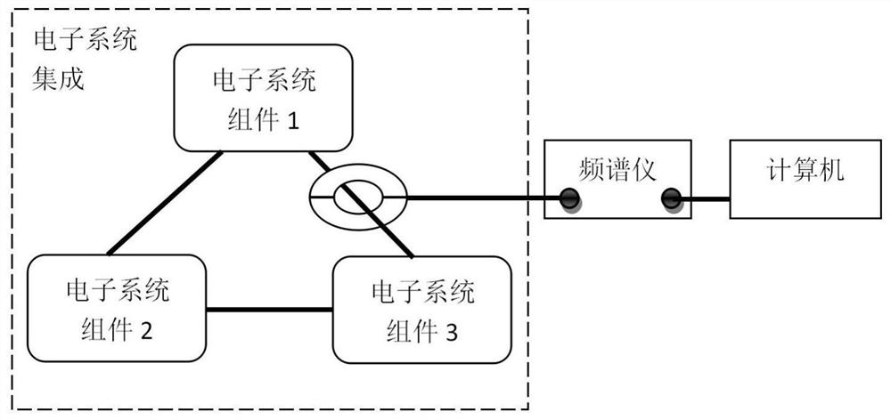
[0046] Such as figure 1 As shown, a method suitable for electromagnetic interference monitoring and interference location during electronic system integration debugging is characterized in that it includes at least the following steps:

[0047] 1) Install the cable caliper at the interconnection cable of the main equipment, and the cable caliper should be within 5cm to 10cm from the cable output port of the main equipment;

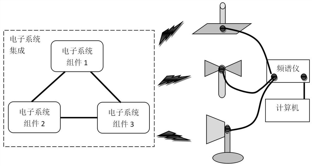
[0048] 2) The cable caliper is connected to the input end of the spectrum analyzer through a coaxial cable. The test range of the spectrum analyzer should be 10kHz-100MHz or 100MHz-400MHz, and the test frequency range should match the corresponding cable caliper. The specific connection layout is as follows: figure 2 shown.

[0049] 3) Place the receiving antenna about 1m away from the system. For the 10kHz~30MHz frequency band, use a rod whip antenna; for 30MHz~1GHz, use a biconical antenna; for 1GHz~18GHz, use a double ridge horn antenna; From 18GHz t...


PUM


Abstract

The invention discloses an electromagnetic interference monitoring and positioning method. Space radiation electromagnetic interference and cable conduction electromagnetic interference are respectively carried out by utilizing a group of detection antennas and cable calipers, wavelet denoising, template matching analysis and other technologies are fused, monitoring and rapid positioning of electromagnetic interference occurring in the assembling and integrating process of a system electronic system are achieved, and theoretical, method and technical supports are provided for effectively improving the electromagnetic environment adaptability of the development cycle of the electronic system. The method can be used for providing an online diagnosis method and technical support for electromagnetic interference occurring in the integrated debugging process of the electronic system, the diagnosis and positioning efficiency of the electromagnetic interference in the integrated debugging process of the electronic system can be greatly improved, the electromagnetic environment adaptability of the electronic system is effectively improved, and an electromagnetic interference monitoring andpositioning flow chart is shown in Figure 1.

Description

technical field [0001] The invention belongs to the technical field of electromagnetic environment detection, and in particular relates to an electromagnetic interference monitoring and positioning method based on wavelet denoising and template matching technology, specifically an electromagnetic interference monitoring and positioning method. Background technique [0002] As the design of electronic systems becomes more and more complex, each component and subsystem has been well designed for electromagnetic interference emission during the development process, but in the process of system integration and debugging, some components and subsystems are often interfered, resulting in the failure of the entire system normal. Due to the limitation of the site and other factors during the system integration process, it is impossible to carry out related work inside the darkroom. This requires an integrated debugging site electromagnetic interference monitoring and rapid position...

Claims


Application Information

Patent Timeline
Patent Type & Authority Applications(China)
IPC IPC(8): G01R31/00G01R29/08
CPCG01R29/0814G01R31/001
Inventor 陈鑫邱扬田锦李金洲左江江
Owner XIDIAN UNIV
Why Eureka
Try Eureka