Methods and systems for reducing conducted electromagnetic interference

a technology of electromagnetic interference and conductance, applied in the direction of dynamo-electric components, dynamo-electric machines, electrical equipment, etc., can solve the problems of undesirable electromagnetic interference, adversely affecting other electronic circuit components, and electric nois

Active Publication Date: 2015-11-03
REGAL BELOIT AMERICA
View PDF12 Cites 6 Cited by
  • Summary
  • Abstract
  • Description
  • Claims
  • Application Information

AI Technical Summary

Problems solved by technology

Such electrical noise can adversely affect other electronic circuit components either within the electronic device itself or in nearby external electronic devices.
In connection with electric power supplies, EMI is undesirable because, for example, it can disturb the operation or degrade the performance of other equipment connected to the same source of power.
However, as a demand for smaller, more compact electric motors increases, manufacturers are limited in EMI filter design, size, and cost.

Method used


Image

  • Methods and systems for reducing conducted electromagnetic interference
  • Methods and systems for reducing conducted electromagnetic interference
  • Methods and systems for reducing conducted electromagnetic interference

Examples


Embodiment Construction

[0011]The embodiments described herein relate generally to reduction of electromagnetic interference (EMI), and more specifically, to reducing conducted EMI in electronically commutated motors and switching power supplies. Although generally described herein with reference to a motor, the methods and systems for reducing EMI described herein may be used to reduce EMI in a variety of electrical apparatus, including for example, switching power supplies, linear power supplies, etc.

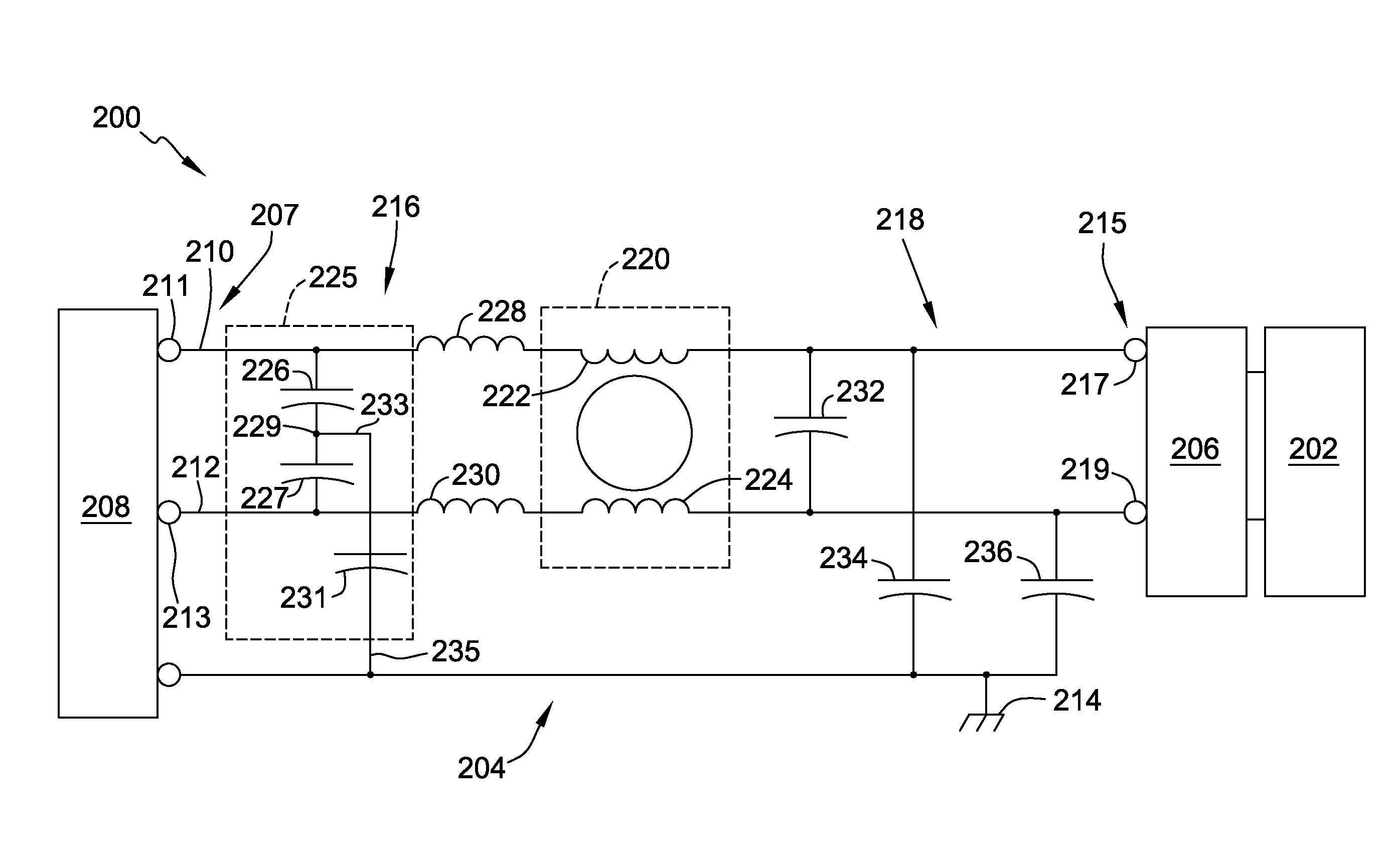
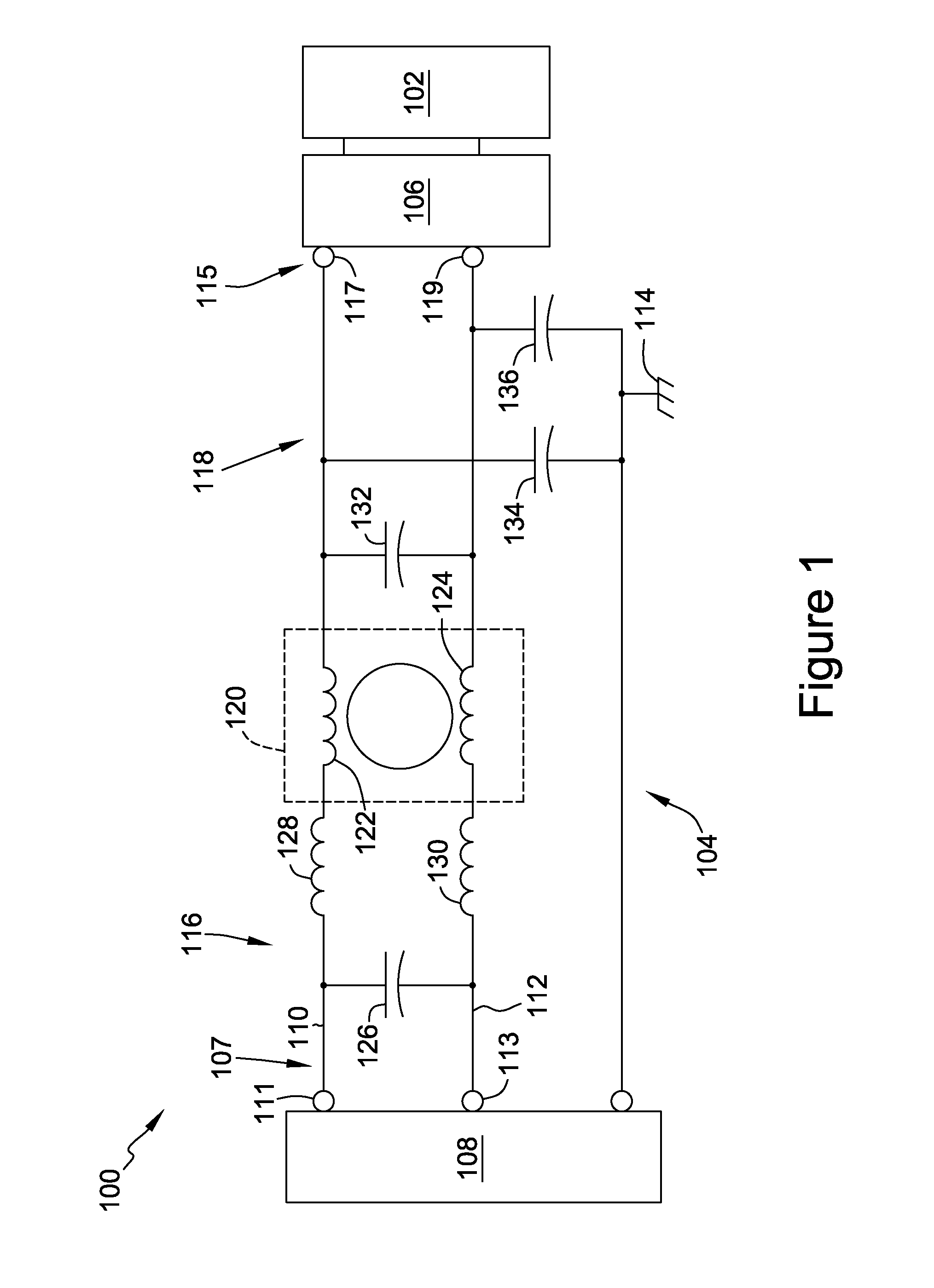
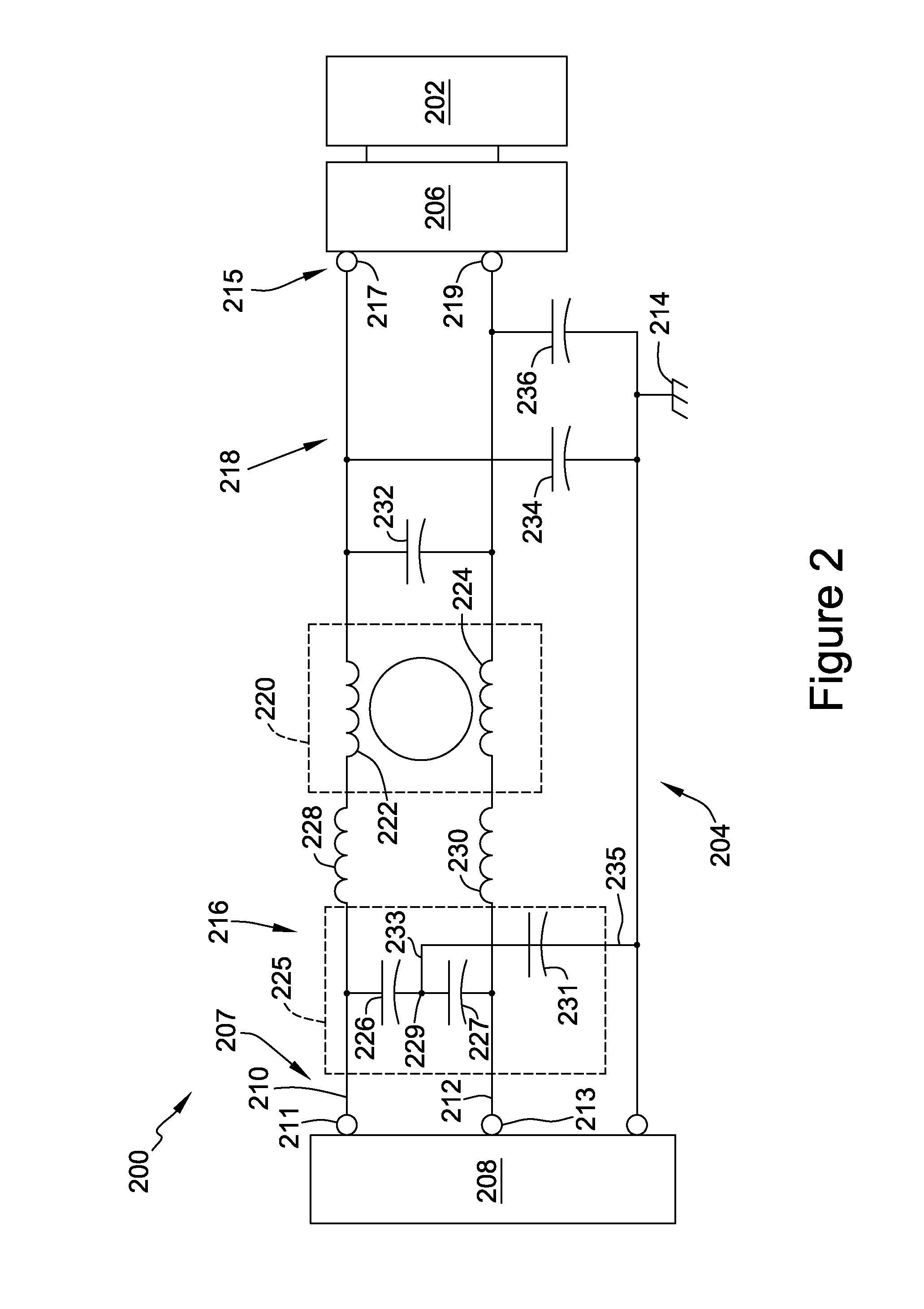
[0012]FIG. 1 is a circuit diagram of a known motor assembly 100 including an electric motor 102, an EMI filter 104, and a motor controller 106. Motor assembly 100, and more particularly EMI filter 104, is coupled at an input 107 to a power supply 108, which is a single phase alternating current (AC) power supply that inputs AC power to a first conductive path 110 and a second conductive path 112. Input 107 includes a first input terminal 111 and a second input terminal 113. Power supply 108 is also coupled t...


PUM


Abstract

An EMI filter is described. The filter includes an input, an output, first and second line-side X capacitors, and a line-side Y capacitor. The input includes first and second input terminals. The output includes first and second output terminals. A first conductive path is defined between the first input terminal and the first output terminal. A second conductive path is defined between the second input terminal and the second output terminal. The first line-side X capacitor is coupled between the first conductive path and the second conductive path, and the second line-side X capacitor is coupled between the first conductive path and the second conductive path in series with the first line-side X capacitor. The second line-side X capacitor is coupled to the first line-side X capacitor at a common point. A first end of the line-side Y capacitor is coupled to the common point.

Description

BACKGROUND OF THE DISCLOSURE[0001]The embodiments described herein relate generally to reduction of electromagnetic interference (EMI), and more specifically, to reducing conducted EMI in electronically commutated motors and switching power supplies.[0002]At least some known electronic devices include electrical lines that produce unwanted electrical noise. Such electrical noise can adversely affect other electronic circuit components either within the electronic device itself or in nearby external electronic devices. Conducted EMI is an electrical noise current which is typically present in the radio-wave frequency range and sometimes referred to as radio frequency interference (RFI). This current originates from within a system of electrical devices rather than from an outside source such as a radio signal transmitter. Electric power supplies of electric motors are sometimes significant generators of EMI. In connection with electric power supplies, EMI is undesirable because, for ...

Claims


Application Information

Patent Timeline
Patent Type & Authority Patents(United States)
IPC IPC(8): H02K11/02H03H7/01H03H7/42
CPCH03H7/427H03H7/0138H02K11/02H02K11/024H02K11/04H02K11/026H02K11/028
Inventor NARDIN, STEVEN A.
Owner REGAL BELOIT AMERICA
Why Eureka
Try Eureka