Optical fiber cleaver

a technology of optical fiber and cleaver, which is applied in the direction of manufacturing tools, instruments, transportation and packaging, etc., can solve the problems of optical fiber giving undesired scratches, omission of sliders, and inability to obtain uniform mirror surfaces

Inactive Publication Date: 2003-10-21
FURUKAWA ELECTRIC CO LTD
View PDF9 Cites 44 Cited by
  • Summary
  • Abstract
  • Description
  • Claims
  • Application Information

AI Technical Summary

Problems solved by technology

For example, in the cleaver shown in FIG. 6, since the pusher G for applying the stress to the optical fiber A is pivoted around the shaft X, when a multi fiber ribbon fiber is handled, due to difference in distance from the fulcrum, bending ...

Method used


Image

  • Optical fiber cleaver
  • Optical fiber cleaver
  • Optical fiber cleaver

Examples


first embodiment

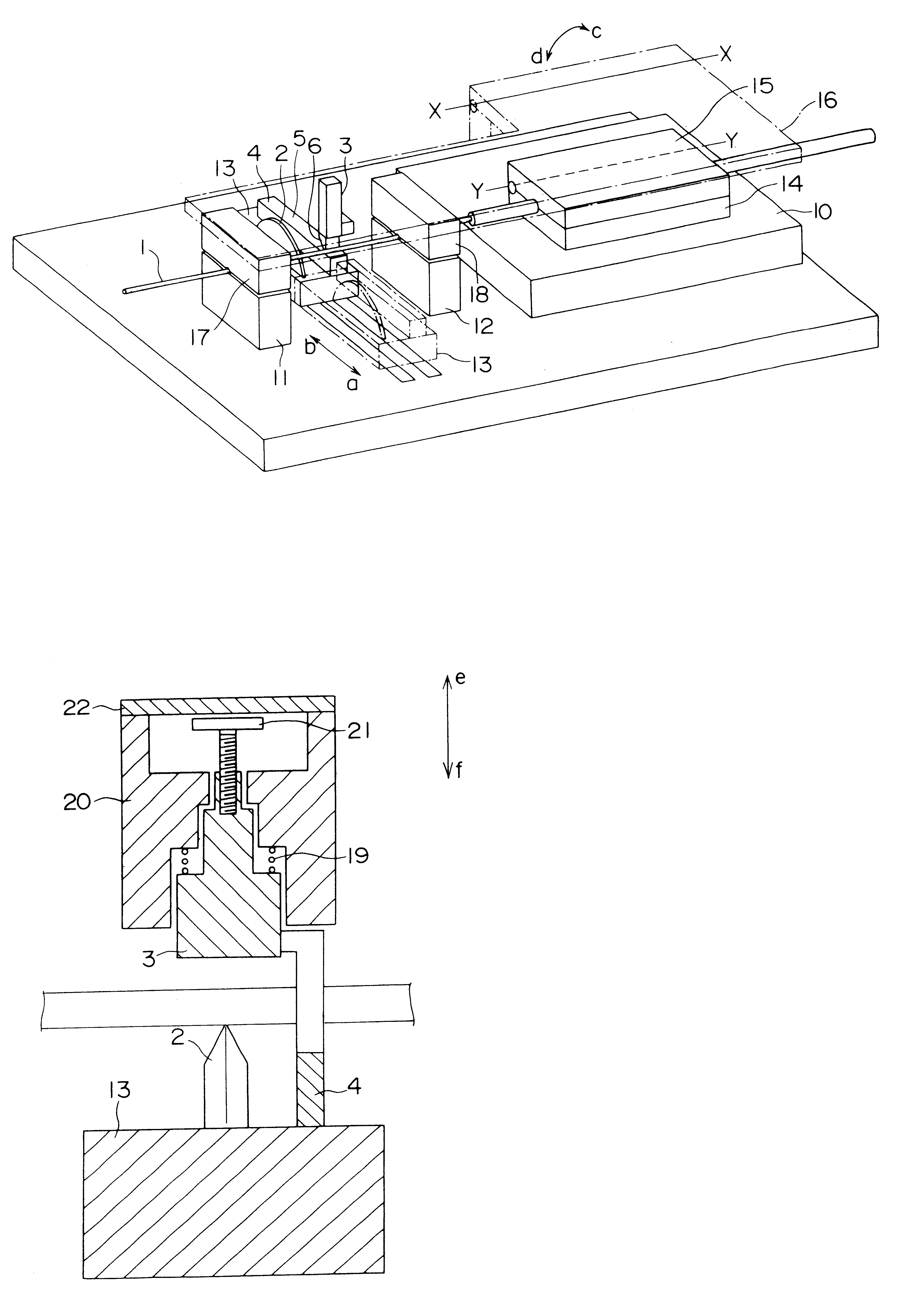
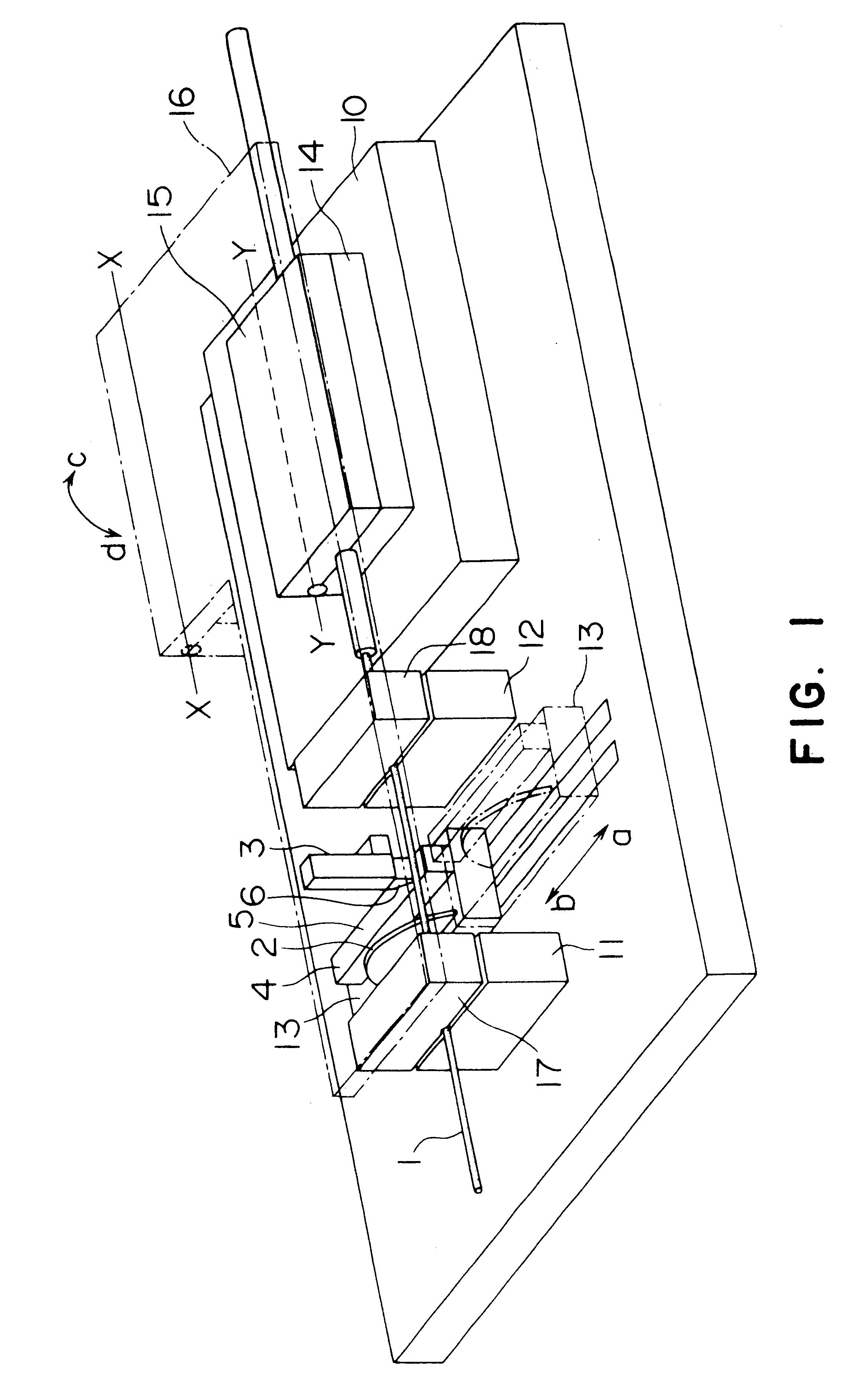
FIG. 1 is a perspective view schematically showing an optical fiber cleaver according to a first embodiment of the present invention. The cleaver comprises fiber resting table 10 on which an optical fiber 1 is laid laterally, and receiving side clamp members 11, 12 for clamping a leading end portion (a portion of the fiber from which a coating was peeled) of the optical fiber 1 set on the fiber resting table 10, and a slider 13 is disposed between the receiving side clamp members 11 and 12 for sliding movement in a direction (a-b direction) perpendicular to an optical axis of the clamped optical fiber 1.

In the fiber resting table 10, the optical fiber 1 is laid on an optical fiber setting portion 14 on the table, and, by pivoting a fiber hold-down member 15 in a direction shown by the arrow c around an axis Y--Y, the optical fiber 1 can be fixed by the fiber hold-down member 15.

Although the receiving side clamp members 11, 12 can receive the leading end portion of the optical fiber ...

second embodiment

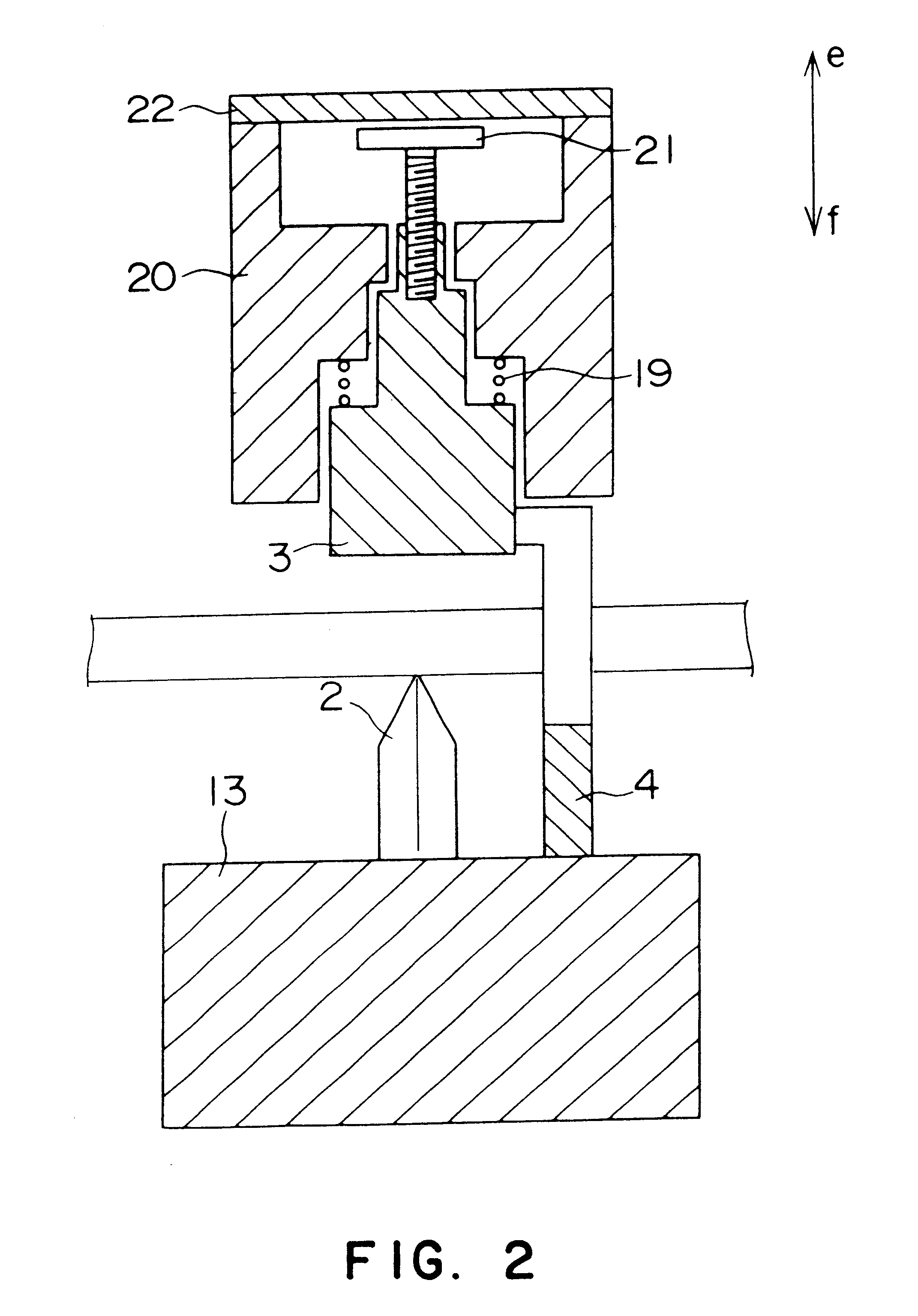
FIG. 4 shows an optical fiber cleaver according to a second embodiment of the present invention, in which the cam 4, pusher 3 and cam follower 6 in the cleaver of FIG. 1 are improved. Similar to the first embodiment, a cam 4 is fixed to the slider 13 and is shaped to have an uneven cam surface as shown in FIG. 4B. A pusher 3 and a cam follower 6 are independently provided on the lid plate 16 so that they can be moved directly along a thickness direction of the lid plate 16 in opposite directions by the presence of a gear 25 therebetween. That is to say, when the cam follower 6 is lifted the pusher 3 is lowered, and, when the cam follower 6 is lowered the pusher 3 is lifted. Incidentally, the cam follower 6 is protruded from a lower surface of the lid plate 16 by a coil spring 26 to be always contacted with the cam 4. Immediately after the slider 13 is slid in the direction a and the blade 2 shown by the broken line in FIG. 4B gives the scratch to the optical fiber 1, the cam followe...


PUM

PropertyMeasurementUnit
Optical propertiesaaaaaaaaaa

Abstract

An optical fiber cleaver, comprising a blade capable of applying a scratch to the outer peripheral surface of an optical fiber and a pusher pushing the optical fiber to cleave it at the scratched part, wherein it further comprises a reverse-running prevention mechanism which prevents the blade which was moved directly and gave scratch to the optical fiber from being directly moved reversely and giving scratch again to the optical fiber, the reverse-running prevention mechanism comprises a cam moved directly in connection with the blade and a cam follower being in contact with the cam and capable of directly moving the pusher, and the cam presses the pusher automatically against the optical fiber for cleavage after the optical fiber has been scratched by the blade and, after the scratch has been given completely, locked with the cam follower so as to suppress the cam from being moved directly in the reverse direction.

Description

1. Field of the InventionThe present invention relates to an optical fiber cleaver for cleaving an optical fiber so that a cleaved section is formed as a mirror surface.2. Description of the Related ArtAn optical fiber has a tendency that, when a scratch is formed on the outer peripheral surface of an optical fiber from which a sheath or coating was peeled and the scratch is grown by pulling or bending the fiber, the fiber is broken at the scratch at once to obtain mirror end surfaces suitable for connection or splicing. In the past, there have been proposed various cleavers for performing such cleaving, including a cleaver proposed by the Inventors, in which a cleaving operation can be facilitated or undesired scratch(s) is not formed in the cleaved surface and therearound. Examples are shown in FIGS. 6 and 7.FIG. 6 shows an example of a cleaver in which the cleaving operation is facilitated and is a view of the cleaver, looked at from an optical axis of an optical fiber A. In this...

Claims


Application Information

Patent Timeline
IPC IPC(8): G02B6/25B26D3/16G02B6/00
CPCG02B6/25Y10T29/5193Y10T29/532Y10T29/5187Y10T29/53243Y10T29/53209Y10T29/514Y10T225/321Y10T225/357
Inventor KAZAMA, JUNICHI
Owner FURUKAWA ELECTRIC CO LTD
Why Eureka
Try Eureka