Control rod for nuclear reactor

a control rod and nuclear reactor technology, applied in nuclear elements, nuclear engineering problems, greenhouse gas reduction, etc., can solve the problems of large likelihood, soundness or integrity of the cladding tube 51, and increase the diameter of the cladding tub

Inactive Publication Date: 2003-10-21
MITSUBISHI HEAVY IND LTD
View PDF3 Cites 50 Cited by
  • Summary
  • Abstract
  • Description
  • Claims
  • Application Information

AI Technical Summary

Problems solved by technology

Furthermore, there is great likelihood that the soundness or integrity of the cladding tube 51 is impaired due to the irradiation.
On the other hand, as the neutron irradiation of the control rod progresses, the neutron absorber expands gradually not only in the axial direction but also in the radial direction to be ultimately brought into contact with the cladding tube, whereby an internal pressure is applied to the cladding tube consequently, the diameter of the cladding tube increases, bringing about strain in the circumferential direction.
Thus, the thickness of the cladding tube at that portion can decrease to such an extent that the control rod 42 within the control rod guide tube 34 may be injured or the control rod 42 jams, giving rise to problems.

Method used


Image

  • Control rod for nuclear reactor
  • Control rod for nuclear reactor
  • Control rod for nuclear reactor

Examples


embodiment 1

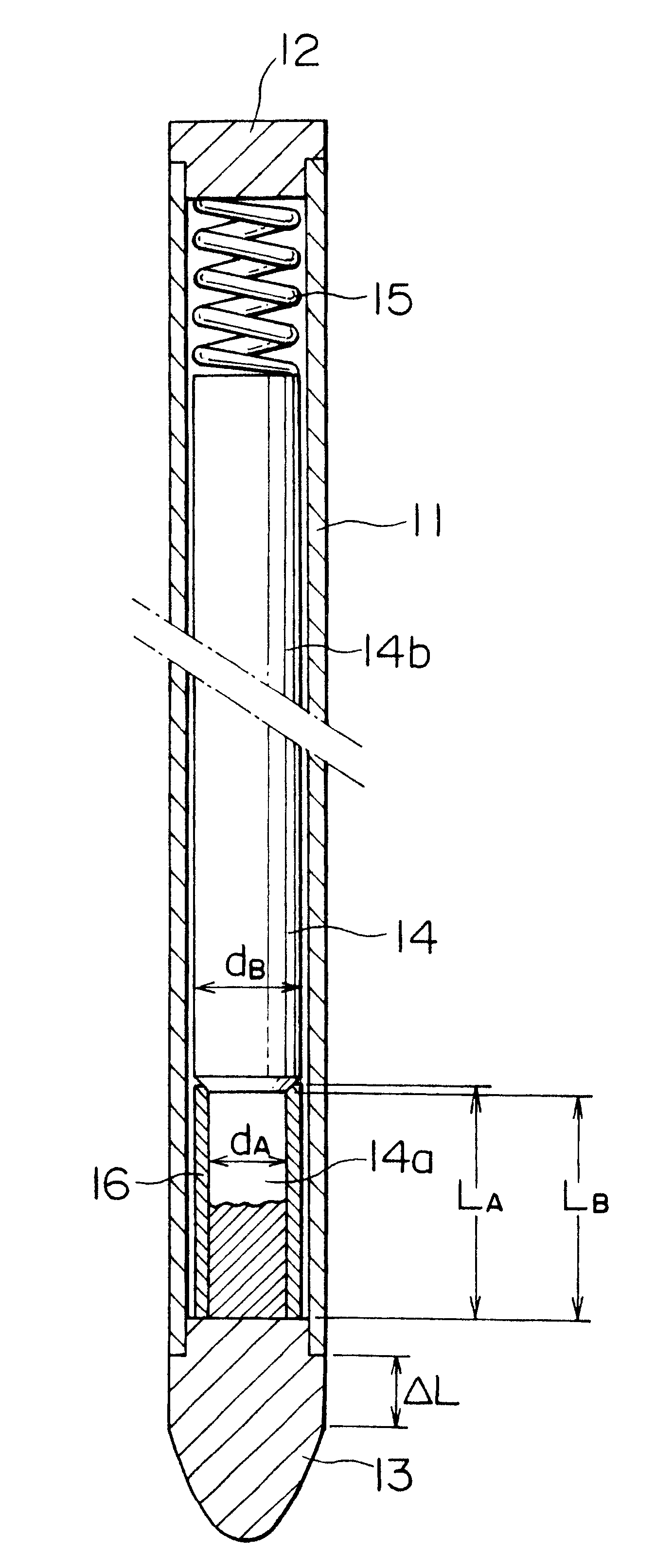
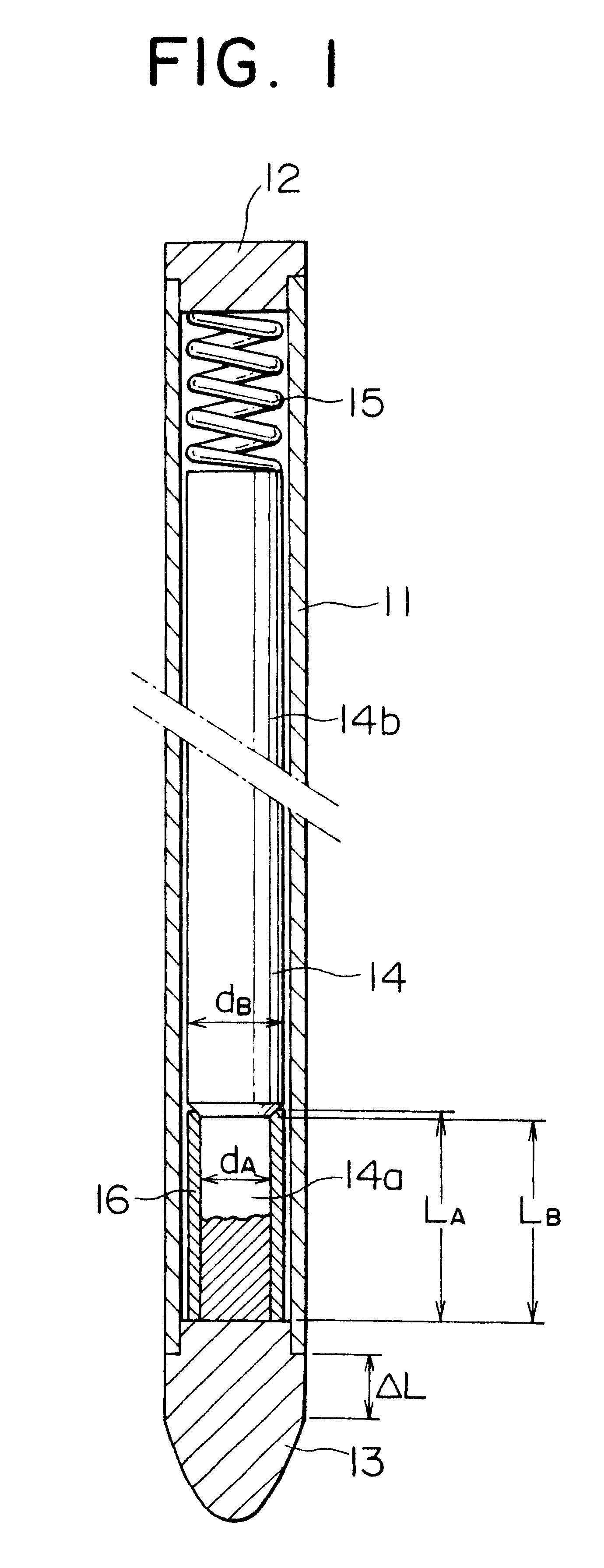
FIG. 1 shows a control rod according to a first embodiment of the present invention. At this juncture, it should be mentioned that the structure of the control rod cluster itself which is constituted by the control rods according to the invention as well as that of the fuel assembly into or from which the control rod cluster is inserted / withdrawn may be same as those known heretofore. Accordingly, for the detail of these structures, reference may have to be made to FIGS. 3 to 5 as occasion requires.

Referring to FIG. 1, the control rod according to the first embodiment of the invention includes a cladding tube 11 formed of stainless steel and hermetically closed at both sides thereof by a top end plug 12 and a bottom end plug 13. Accommodated within the cladding tube 11 is a rod-like neutron absorber 14 according to the instant embodiment of the invention. The neutron absorber 14 is formed of a neutron absorbing material such as an Ag--In--Cd (silver-indium-cadmium) alloy or boron ca...

embodiment 2

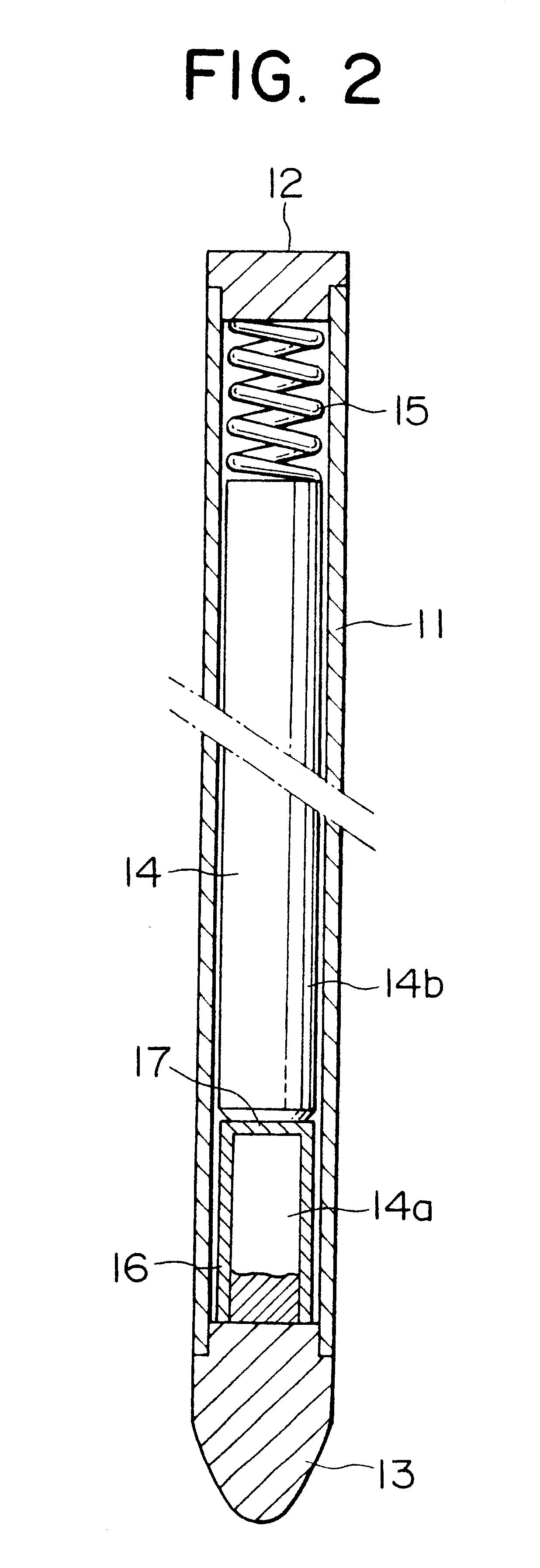
The control rod according to a second embodiment of the present invention will be described by reference to FIG. 2. As can be seen in the figure, the control rods according to the second embodiment are implemented in such a structure that a cladding tube 11 formed of a stainless steel is hermetically closed at both ends by a top plug 12 and a bottom plug 13, respectively, wherein a rod-like neutron absorber is accommodated within the cladding tube 11. The neutron absorber 14 is formed of a neutron absorbing material such as an Ag--In--Cd (silver-indium-cadmium) alloy or boron carbide or the like and pressed downwardly against a bottom plug 13 by means of a hold-down spring 15 disposed within the cladding tube 11 at a top end portion thereof.

Further, the neutron absorber 14 includes a reduced-diameter portion 14a which is located at the side of the bottom end plug and which has a smaller diameter than the other portion of the neutron absorber 14 having an ordinary diameter, wherein a...


PUM


Abstract

A control rod for a nuclear reactor has a structure which is capable of suppressing expansion of a reduced-diameter portion of a neutron absorber in a radial direction under shocks applied upon every stepwise driving of a control rod cluster and which can ensure integrity of a cladding tube over an extended period. The control rod includes a cladding tube closed hermetically at both ends thereof by a top end plug and a bottom end plug, respectively, a neutron absorber loaded into the cladding tube and includes a reduced-diameter portion having a smaller diameter than the other portion, the reduced-diameter portion being disposed at the bottom end plug side of the control rod, and a hold-down spring for pressing the neutron absorber downwardly against the bottom end plug. A sleeve is disposed within an annular space defined between an outer peripheral surface of the reduced-diameter portion and an inner peripheral surface of the cladding tube.

Description

1. Field of the InventionThe present invention generally relates to a nuclear reactor and, more particularly, to a control rod used in a pressurized water reactor.2. Related ArtFor better understanding of the present invention, background techniques thereof will first be described in some detail. A representative example of a fuel assembly employed in a pressurized water reactor is shown in FIG. 3 of the accompanying drawings. As is shown in the figure and also well known in the art, a fuel assembly 31 includes a plurality of control rod guide tubes 34 fixedly held at both ends by an upper nozzle 32 and a lower nozzle 33, respectively, a plurality of fuel rods 35, and a plurality of supporting lattices 36 through which the control rod guide tubes 34 and the fuel rods 35 are inserted, wherein individual control rods 42 constituting, for example, a control rod cluster 41, as shown typically in FIG. 4, are inserted into the control rod guide tubes 34 from the above or withdrawn therefr...

Claims


Application Information

Patent Timeline
Patent Type & Authority Patents(United States)
IPC IPC(8): G21C7/10G21C7/08G21C7/117
CPCG21C7/10G21Y2002/104Y02E30/39G21Y2004/303G21Y2002/303Y02E30/30
Inventor MURAKAMI, KAZUOSUZUKI, SHIGEMITSUYOSHIGAI, KYOHICHI
Owner MITSUBISHI HEAVY IND LTD
Why Eureka
Try Eureka