Nuclear reactor fuel assemblies

a fuel assembly and nuclear reactor technology, applied in nuclear elements, nuclear engineering problems, greenhouse gas reduction, etc., can solve the problem of small gap between baffle structure plates, and achieve the effect of reducing fretting wear

Inactive Publication Date: 2006-08-01
WESTINGHOUSE ELECTRIC CORP
View PDF21 Cites 47 Cited by
  • Summary
  • Abstract
  • Description
  • Claims
  • Application Information

AI Technical Summary

Benefits of technology

[0009]In a preferred embodiment, the intermediate support grid comprises a series of intersecting thin metal straps in an egg crate design that forms square cells around the fuel rods. Coplanar dimples and / or springs contact the fuel rods on multiple sides and provide additional rod support. The location of the grid is fixed relative to the fuel assembly at thimble tube locations. The strap heights of the auxiliary support grids are smaller than that of the main support grids and the auxiliary support grids do not include mixing vanes, which can be found on the main support grids. The outer strap includes guide tabs to prevent hang-up with adjacent fuel assemblies during removal or insertion respectively out of or into the reactor core. The inner strap is designed to help eliminate fretting wear by increasing the contact area of the spring / dimple with the fuel rod over the corresponding contact area on the main support grids.

Problems solved by technology

These bolts sometimes become loose, thereby developing a small gap between the baffle structure plates.
The fluid jetting, when it impinges on the outer row of fuel assemblies in the core, makes the outer fuel rods vibrate, eventually causing them to fail.

Method used


Image

  • Nuclear reactor fuel assemblies
  • Nuclear reactor fuel assemblies
  • Nuclear reactor fuel assemblies

Examples


Embodiment Construction

[0018]In the following description, like reference characters designate like or corresponding parts throughout the several views of the drawings. Also in the following description, it is to be understood that such terms as “forward”, “rearward”, “left”, “right”, “upwardly”, “downwardly” and the like are words of convenience and are not to be construed as limiting terms.

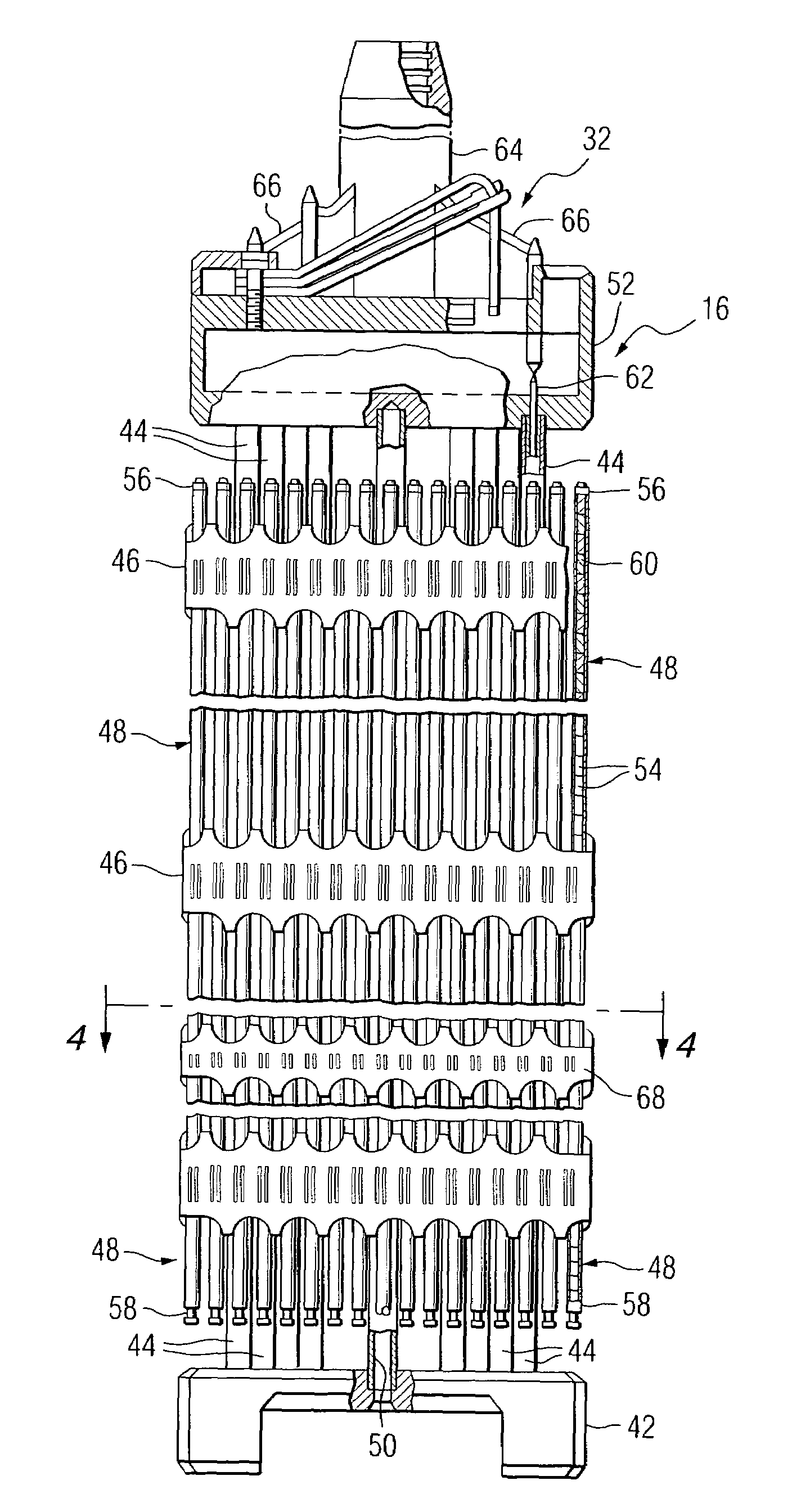
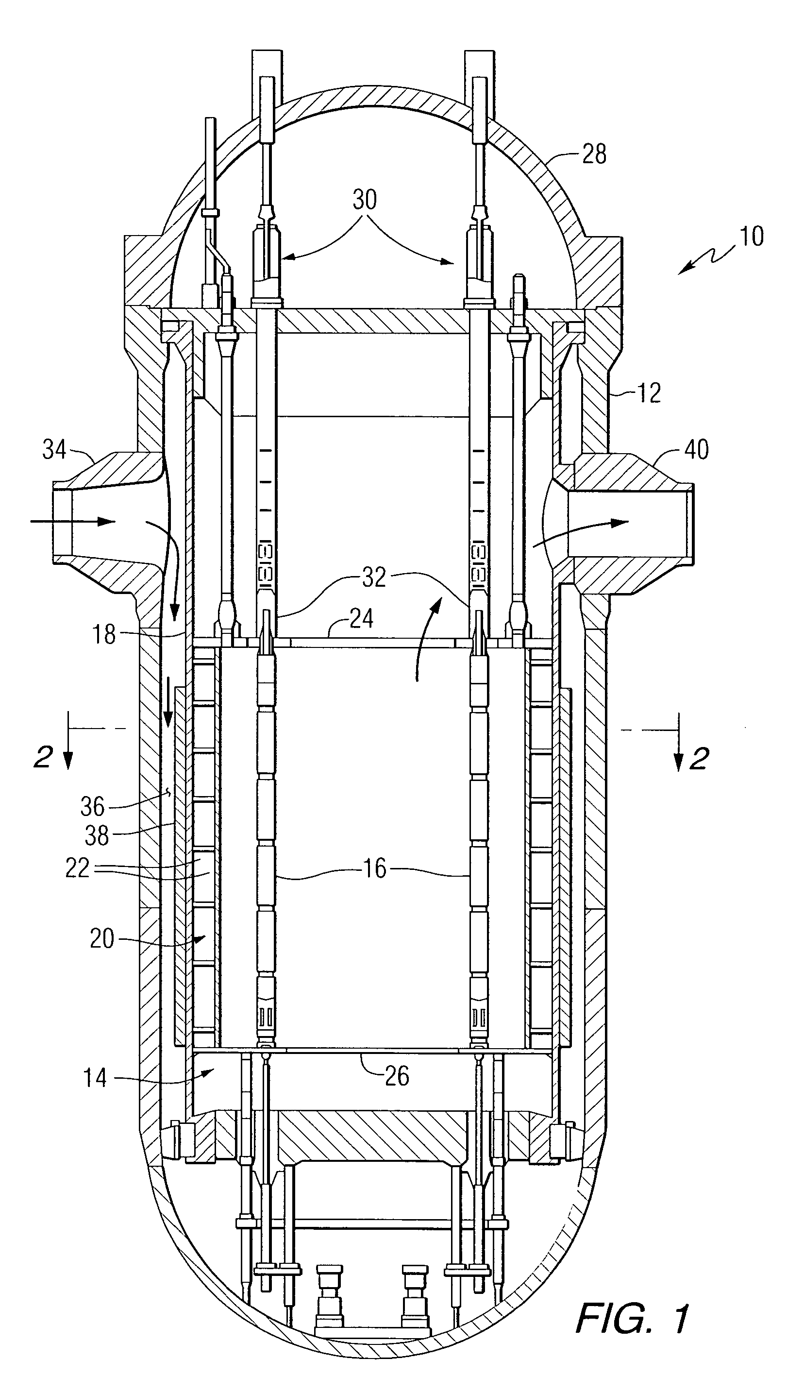
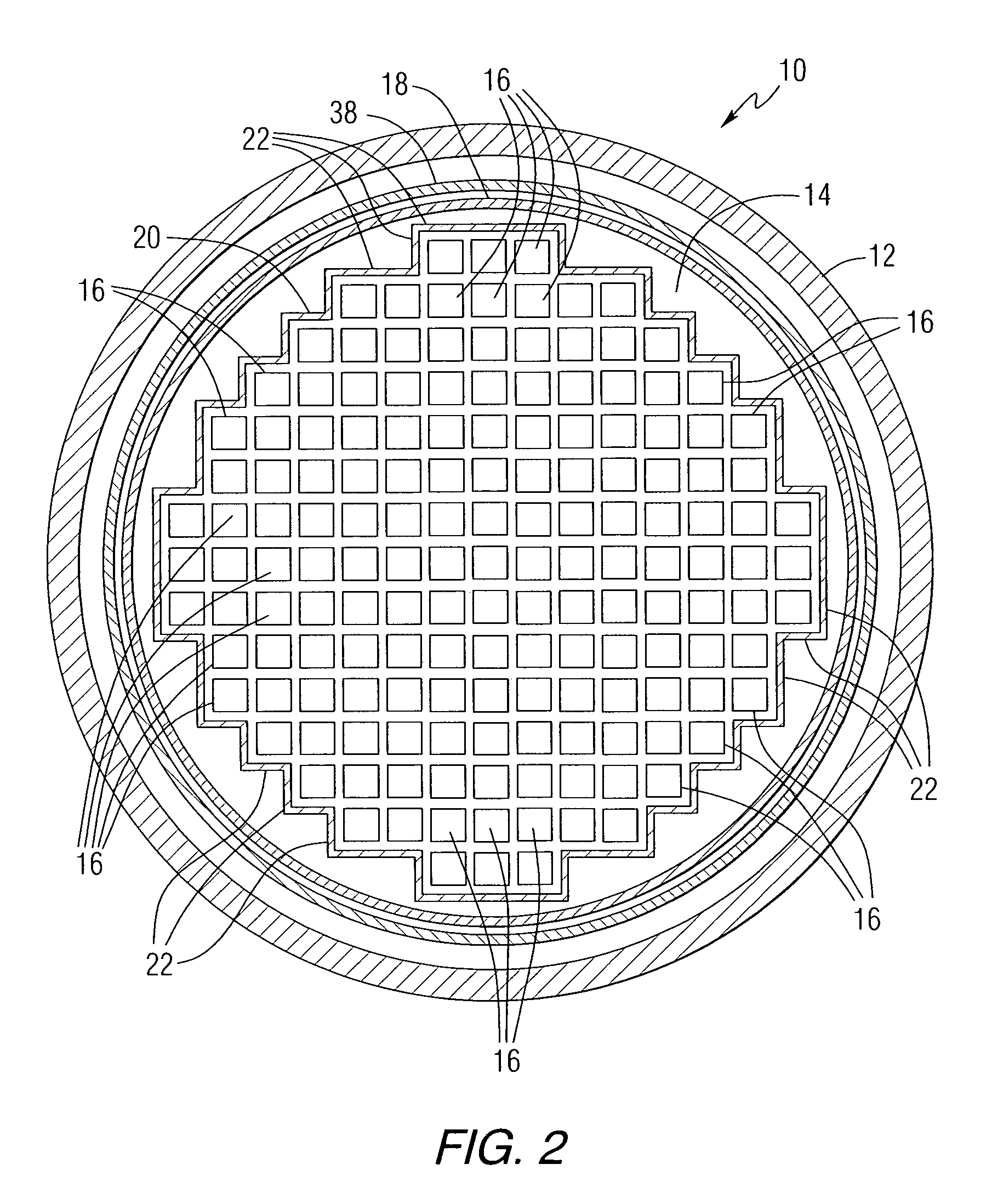
[0019]Referring now to the drawings, and particularly to FIGS. 1 and 2, there is shown a pressurized water nuclear reactor (PWR) being generally designated by reference character 10. The PWR 10 includes a reactor pressure vessel 12 which houses a nuclear reactor core 14 composed of a plurality of elongated fuel assemblies 16. The relatively few fuel assemblies 16 shown in FIG. 1 are for purposes of simplicity only. In actuality, as schematically illustrated in FIG. 2, the core 14 is composed of a great number of fuel assemblies 16.

[0020]Spaced radially, inwardly from the reactor vessel 12 is a generally cylindrical co...


PUM


Abstract

A nuclear fuel assembly having a parallel array of elongated fuel elements supported between an upper and lower nozzle. Main support grids are substantially evenly spaced along the elongated dimension of the assembly to maintain the spacing between fuel elements. A plurality of auxiliary vibration-resistant grids respectively positioned between the main support grids in the middle third elongated dimension of the fuel elements, that are smaller in height and provide a larger fuel element contact area than the main support grids.

Description

BACKGROUND OF THE INVENTION[0001]1. Field of the Invention[0002]The present invention relates generally to fuel assemblies for a nuclear reactor and, more particularly, is concerned with fuel assemblies positioned adjacent the baffle structure about the periphery of the reactor core, which employ anti-vibration grids.[0003]2. Related Art[0004]A typical nuclear power reactor includes a reactor vessel housing a nuclear reactor core. Spaced radially, inwardly from the reactor vessel is a generally cylindrical core barrel and within the barrel is a former and a baffle system (hereafter called the “baffle structure”), which permits transition from the cylindrical barrel to a squared-off periphery of the reactor core formed by the fuel assemblies arrayed therein.[0005]The reactor core is composed of a large number of elongated fuel assemblies. Each fuel assembly includes a plurality of fuel rods containing the fissile material, which reacts to produce heat. The fuel rods of each fuel asse...

Claims


Application Information

Patent Timeline
Patent Type & Authority Patents(United States)
IPC IPC(8): G21C3/34G21C3/33G21C3/356
CPCG21C3/356Y02E30/40G21Y2004/304G21Y2002/303Y02E30/30G21C3/34
Inventor GOLDENFIELD, MARK P.NGUYEN, QUANG M.SETTLE, GREGORY E.POMIRLEANU, RADU O.ELMAHDI, ABDELAZIZ M.WALTON, LEWIS A.BRASHIER, RAYMOND W.
Owner WESTINGHOUSE ELECTRIC CORP
Why Eureka
Try Eureka