Fastener installation apparatus

a technology of installation apparatus and fastener, which is applied in the direction of fastener tools, manufacturing tools, metal-working machine components, etc., can solve the problems of limited life in mass production applications, inability to include a sensor, such as a proximity probe, in the design of the installation head disclosed in this patent, and the subject to alignment problems. , to achieve the effect of reducing the space required for the installation apparatus and reducing the wear of the guide shank

Active Publication Date: 2006-02-07
PENN AUTOMOTIVE INC
View PDF26 Cites 6 Cited by
  • Summary
  • Abstract
  • Description
  • Claims
  • Application Information

AI Technical Summary

Benefits of technology

[0009]As described above, the fastener installation apparatus of this invention is designed to solve two separate problems associated with self-attaching fastener installation heads, namely the application of two or more adjacent self-attaching fasteners in a panel in close proximity and the elimination of wear or damage to the proximity probe or debris interfering with sensing of a fastener in the plunger passage. First, the fastener installation apparatus of this invention may be utilized to simultaneously install a plurality of self-attaching fasteners in a panel in relatively close proximity. In one preferred embodiment of the fastener installation apparatus of this invention, the plunger includes at least two spaced generally parallel projecting end portions or legs adapted to be fixed relative to a fixed member. As will be understood by those skilled in this art, the plunger may be attached or releasably attached to the fixed member or abut the fixed member during reciprocal motion of the plunger through the plunger passage and thus adapted to be fixed relative to the fixed member. Further, where it is desirable to simultaneously install more than two fasteners in a panel, the plunger would have more than two spaced generally projecting end portions or a plurality of spaced generally parallel projecting end portions. In one disclosed embodiment of the plunger, the plunger is generally shaped including a body portion fixed relative to the fixed member having at least two spaced generally parallel legs or projecting end portions preferably integral with a body portion. In a second, more preferred embodiment of the fastener installation apparatus of this invention, the plunger assembly comprises at least two separate parallel plungers in close proximity each having a base or support portion which, in the disclosed embodiment is cylindrical, received in a configured opening in the fixed member and a leg or plunger portion telescopically receivable in a plunger passage. In the disclosed embodiment, the leg portion of the plungers is rectangular in cross-section, permitting rotation of the plunger 180° if the cutting edge is damaged. Further, this embodiment assures accurate alignment of the plungers of the plunger assembly and eliminates fasteners which may shear under heavy loading.
[0011]In the disclosed embodiment, the fastener installation apparatus includes a guide shank having one end attached to a moveable member having a bore which receives a coil spring resiliently biasing the moveable member away from the fixed member and the fastener installation apparatus includes a bushing surrounding the guide shank reducing wear of the guide shank and accurately guiding movement of the moveable member relative to the fixed member as disclosed in the above-referenced U.S. Pat. No. 6,442,830. However, the principle of simultaneously installing a plurality of self-attaching fasteners with the fastener installation apparatus of this invention may also be utilized with other types of self-attaching fastener installation heads.
[0012]A preferred embodiment of the fastener installation apparatus of this invention also includes a fastener sensor system which senses the presence of a fastener in the plunger passage or plunger passages, but avoids failure of the sensor system resulting from wear or damage to the sensor or false sensing resulting from build up of chips or debris in the plunger passage. In one preferred embodiment, the fastener installation apparatus includes a sensor, such as a proximity probe, which extends generally perpendicular to the plunger passage and the feed passage having an end portion adjacent to, but spaced from the plunger passage, sensing a presence of a fastener in the plunger passage without the fastener contacting the sensor. The assembly further includes a stop surface opposite the feed passage, defining a surface of the plunger passage, limiting movement of the fastener from the feed passage to the plunger passage, such that the fastener may engage the stop surface, rather than the sensor. In the disclosed embodiment, the sensor is an elongated proximity probe having a longitudinal axis extending generally perpendicular to the plunger passage and the feed passage having an end portion adjacent to, but spaced from the plunger passage. In the disclosed embodiment, the proximity probes are cylindrical, but may have any conventional shape. Thus, the self-attaching fasteners received in the plunger passage do not contact the proximity probe, eliminating wear of the proximity probe and false readings from the sensor. Where the fastener installation apparatus of this invention simultaneously installs at least two self-attaching fasteners in a panel, as described above, the fastener installation apparatus includes a sensor adjacent to but spaced from each of the plunger passages. However, the improved sensor may also be utilized in the fastener installation apparatus disclosed in the above-referenced U.S. Pat. No. 6,442,830. Another advantage of the sensor system of this invention is that the lines or wires from the proximity probes extend from the moveable member generally perpendicular to the plunger passages, reducing the space required for the installation apparatus.

Problems solved by technology

However, the pressure pierce installation head disclosed in U.S. Pat. No. 4,505,416 had several problems including wear of the guide shanks or bolts resulting in limited life in mass production applications and the moveable member, which includes a feed passage, is formed of a single block of metal requiring replacement of the entire moveable member in the event of damage to the moveable member.
Also, the pressure pierce installation head disclosed in this patent is subject to alignment problems because the plunger was not sufficiently guided by the guide bolts for rugged use in mass production applications.
Another problem was that it was not practical to include a sensor, such as a proximity probe, in this head design.
However, this conventional arrangement results in wear or damage to the proximity probe in mass production applications.
Further, the leg of the plunger required a machined slot to clear the proximity probe during actuation, resulting in additional expense.
Another problem associated with all conventional installation apparatus for self-attaching fasteners is installing self-attaching fasteners in close proximity in a panel.
In a conventional self-attaching fastener installation head, the spacing of the fasteners in a panel is limited by the size of the nose or moveable member.

Method used


Image

  • Fastener installation apparatus
  • Fastener installation apparatus
  • Fastener installation apparatus

Examples


Embodiment Construction

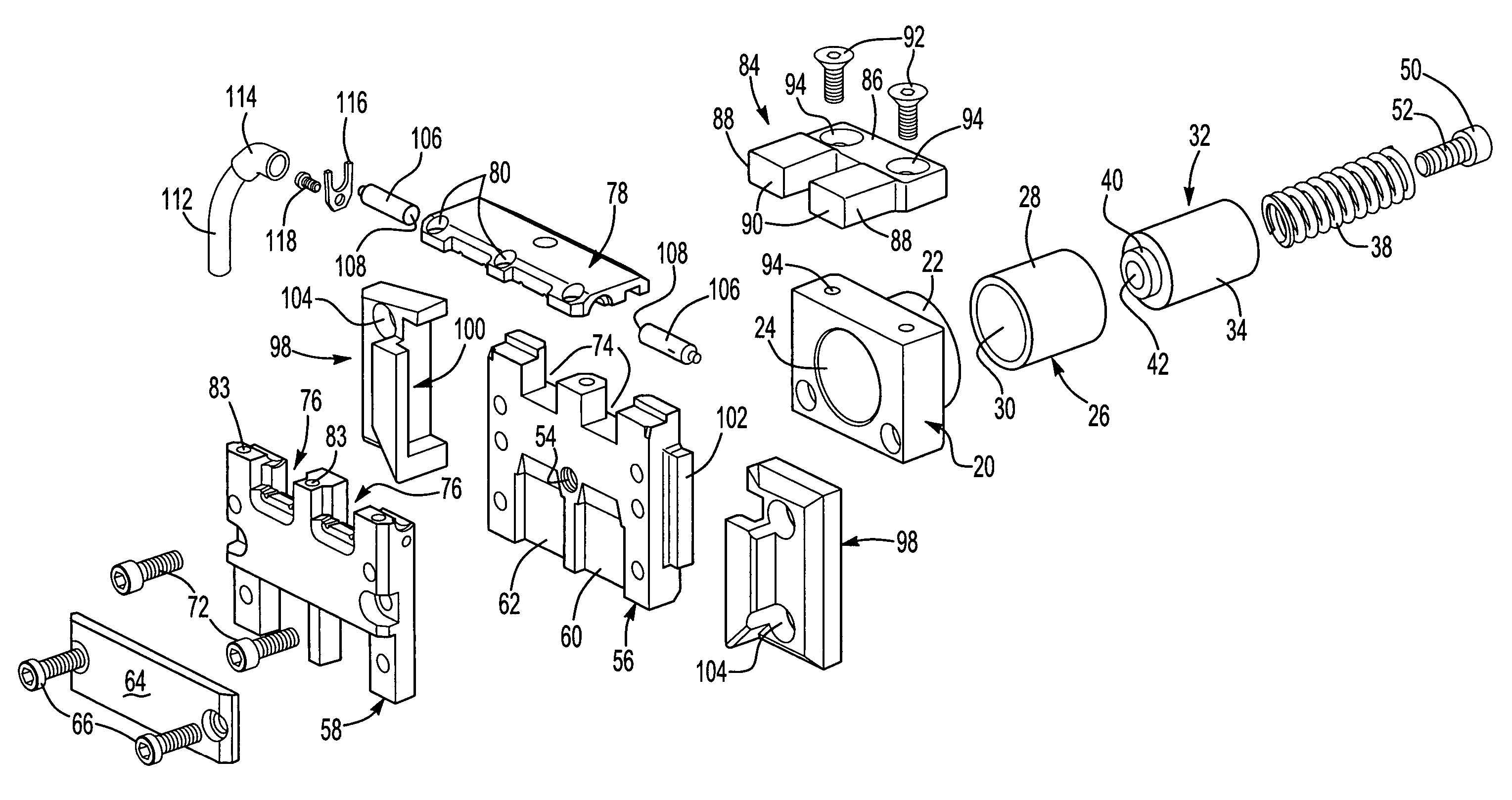
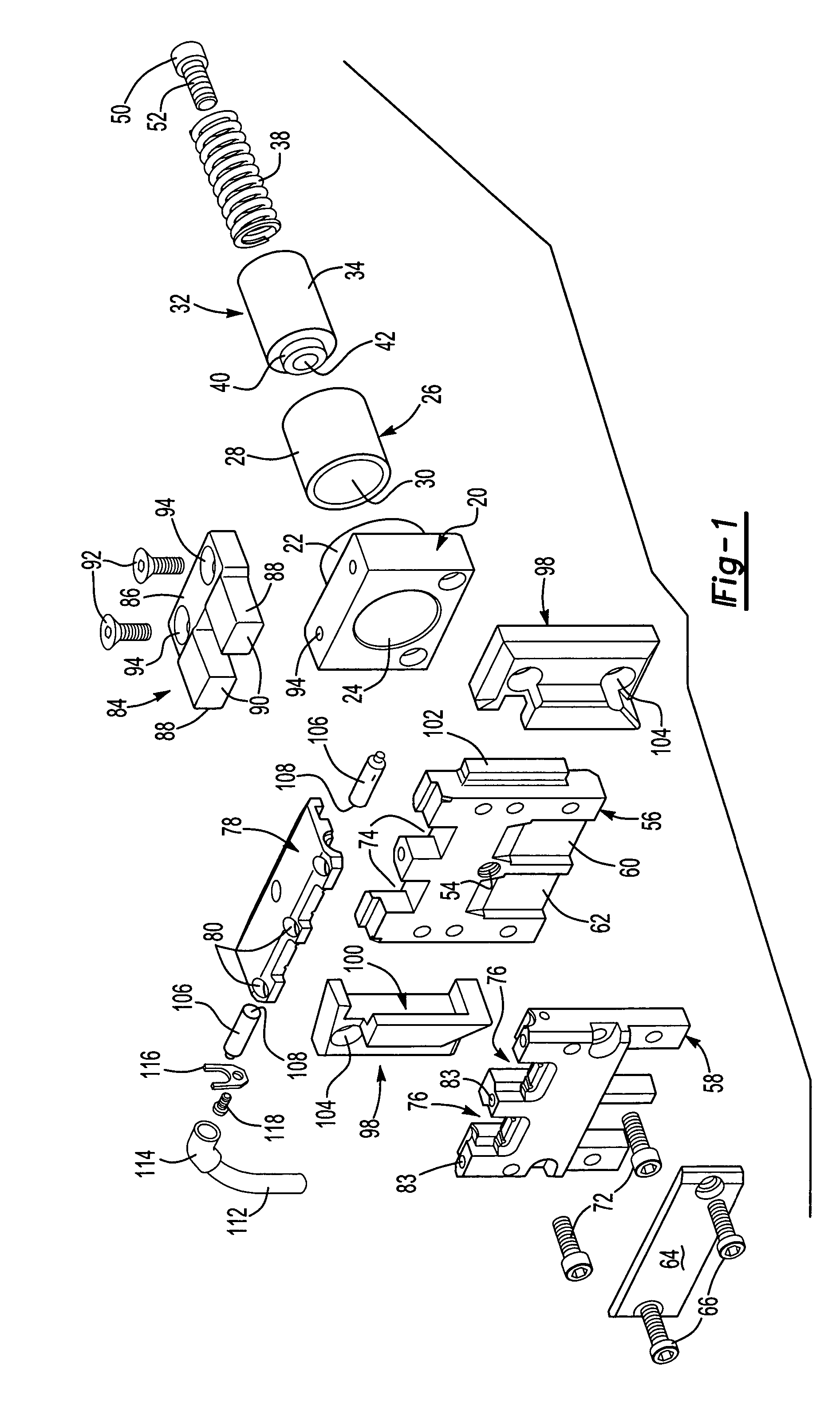
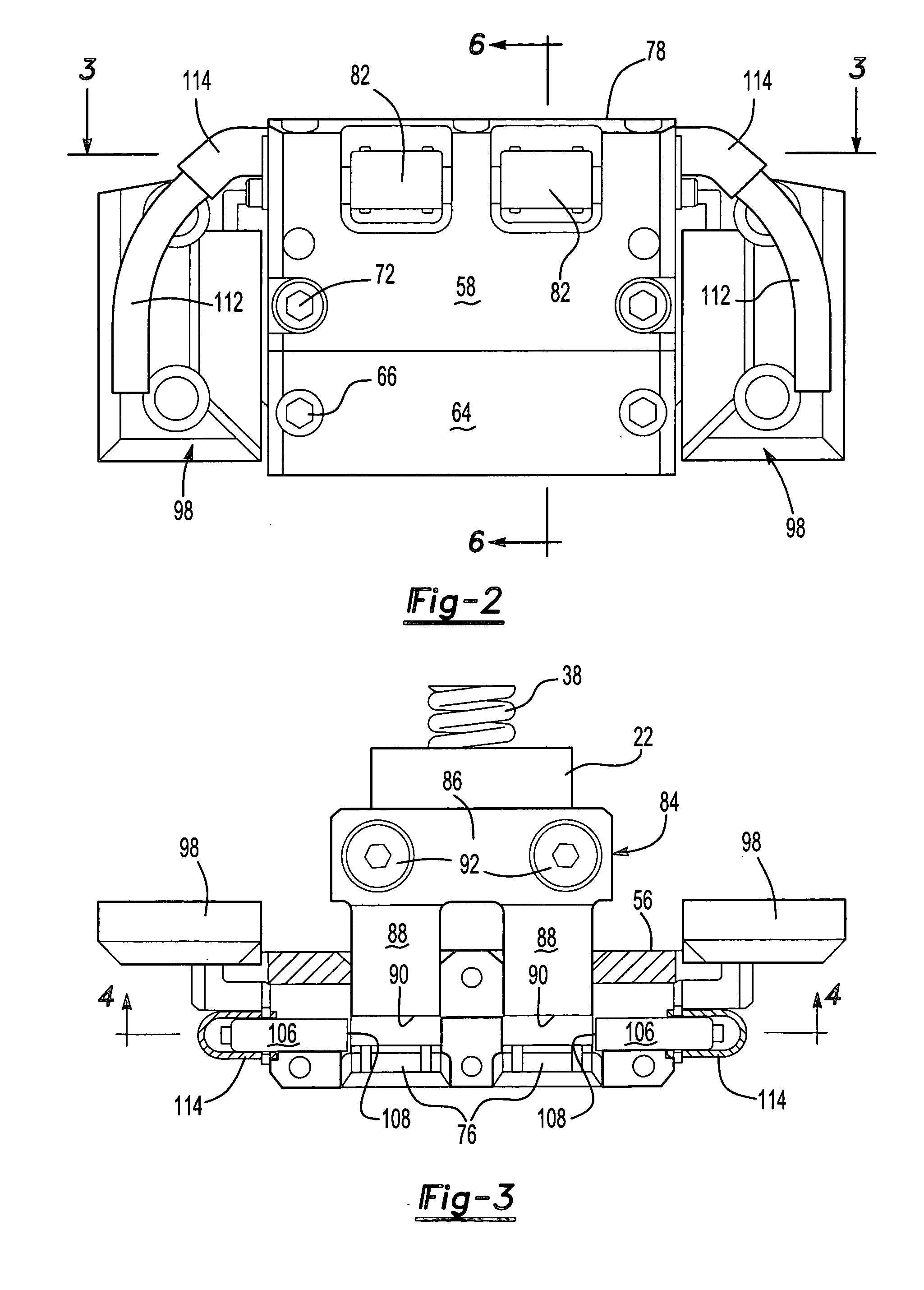
[0022]The disclosed embodiments of the fastener installation apparatus of this invention is adapted to install self-attaching fasteners in a metal panel in mass production applications, such as utilized by the automotive and appliance industries. The above-referenced patents disclose several types of self-attaching nuts available from the assignee of this patent application. However, the fastener installation apparatus may be adapted to install various types of self-attaching fasteners, including but not limited to pierce and clinch nuts. As set forth above, the fastener installation apparatus of this invention is particularly, but not exclusively, adapted for installation of self-attaching fasteners where the space available for the installation head is limited or restricted, such that the stroke of the plunger assembly which engages and installs the self-attaching fastener in a panel opposite the plunger passage, is relatively short when compared to conventional pierce nut install...


PUM

PropertyMeasurementUnit
movementaaaaaaaaaa
sizeaaaaaaaaaa
widthaaaaaaaaaa

Abstract

The disclosed fastener installation apparatus includes a plurality of spaced parallel feed passages each communicating with a plunger passage in a moveable member and the fixed member includes a plunger assembly having a plurality of spaced parallel legs which reciprocate through the plunger passages to simultaneously install a plurality of fasteners in a panel opposite the plunger passage. In one embodiment, the plunger assembly includes a body portion fixed to the fixed member and a plurality of integral parallel legs and a second embodiment having a plurality of separate spaced parallel plungers. Each plunger passage includes a proximity probe having an end adjacent to, but spaced from the plunger passage eliminating wear or damage to the proximity probes during use.

Description

FIELD OF THE INVENTION[0001]This invention relates to fastener installation apparatus for installing self-attaching fasteners, including pierce and clinch nuts particularly, but not exclusively, for applications in a confined space where a conventional fastener installation apparatus cannot be used.BACKGROUND OF THE INVENTION[0002]Fastener installation apparatus for installing self-attaching fasteners in mass production applications, such as automotive applications, typically include a fastener installation head which includes a reciprocating plunger for installing a self-attaching fastener in a panel opposite the plunger passage, and a die member or die button which supports the panel and deforms the panel into a recess provided in the fastener, permanently installing the fastener in the panel. There are several types of self-attaching fasteners, including pierce and clinch nuts as disclosed, for example, in U.S. Pat. No. 3,648,747, assigned to the assignee of the predecessor in in...

Claims


Application Information

Patent Timeline
Patent Type & Authority Patents(United States)
IPC IPC(8): B23P21/00B23P19/00B23P19/04B23P19/06B23Q15/00B25B27/14B25B31/00
CPCB23P19/062Y10T29/5343Y10T29/49837Y10T29/5307Y10T29/53065
Inventor VRANA, JOHN J.
Owner PENN AUTOMOTIVE INC
Why Eureka
Try Eureka