Pneumatic tire

Active Publication Date: 2012-08-30
BRIDGESTONE CORP
View PDF8 Cites 6 Cited by
  • Summary
  • Abstract
  • Description
  • Claims
  • Application Information

AI Technical Summary

Benefits of technology

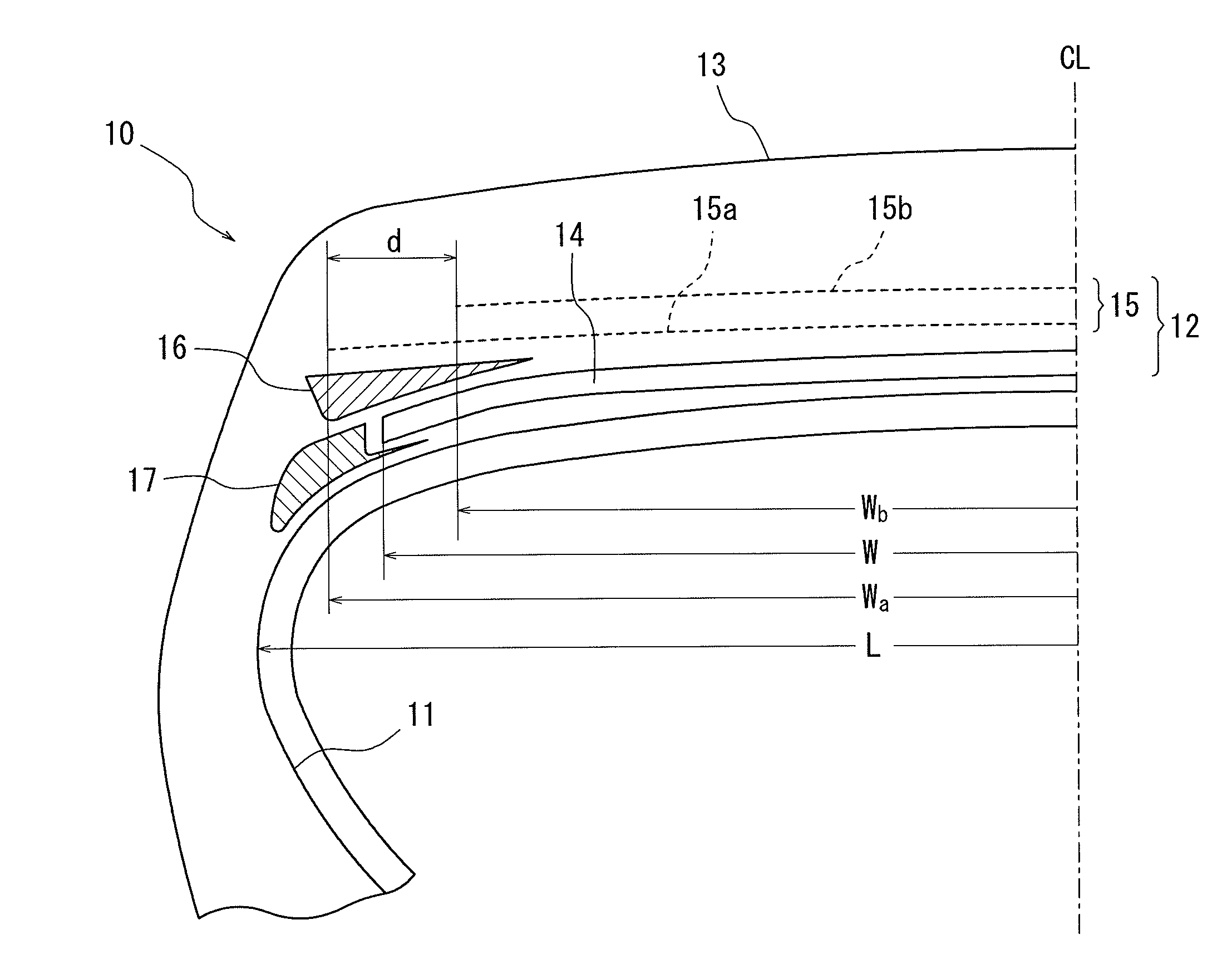
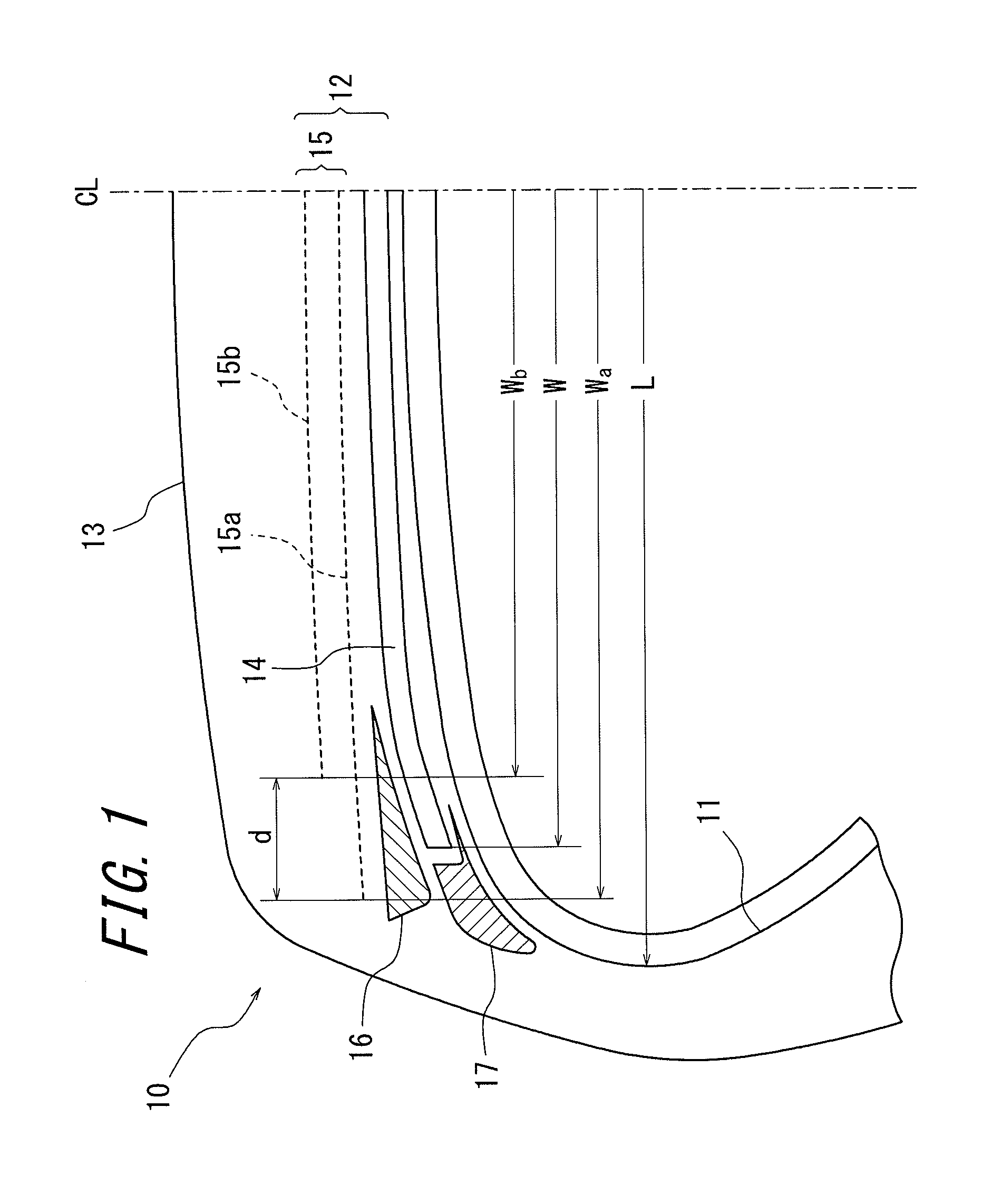
[0018]According to the pneumatic tire of the present invention, a belt width of an intersecting belt having the maximum belt width along the tire width direction among intersecting belt layer is set to 80% or more of the maximum width of a carcass line; a difference in belt widths between the intersecting belt having the maximum belt width and an intersecting belt having the second maximum belt width among the intersecting belt layer is set in the range of 10 mm to 50 mm on one side of the belt in the width direction; the belt width has a relationship in which the intersecting belt having the maximum belt width is not narrower than the circumferential belt, and the circumferential belt is not narrower than the intersecting belt having the second maximum belt width; and the pneumatic tire has an interposed rubber disposed between both end portions of the circumferential belt and r

Problems solved by technology

However, the shear rigidity cannot be sufficiently obtained only with the circumferential belt, and hence, it is necessary to combine the circumferential belt with an intersecting belt to sufficiently obtain the shear rigidity.
The intersecting belt has a high shear rigidity and easily stretches, while the circumferential belt has a low shear rigidity an

Method used


Image

  • Pneumatic tire
  • Pneumatic tire
  • Pneumatic tire

Examples


example

[0048]Two types (Examples 1 and 2) of pneumatic tires 10 according to the present invention were prepared, and were subjected to comparative tests with two types of Conventional Examples (Conventional Examples 1 and 2) and Comparative Example in terms of modulus (mod.) of 100% elongation and loss tangent (tan δ) of the interposed rubber 16 and the side-lower rubber 17.

[0049]FIG. 3 is a diagram for conceptually explaining a belt structure of the prepared pneumatic tires. As illustrated in FIG. 3, the prepared pneumatic tires were ultralow profile radial tires for heavy load with a tire size of 495 / 45R225, and include an intersecting belt layer with three-layered structure (first intersecting belt 15a, second intersecting belt 15b, and third intersecting belt 15c: Example 1) or two-layered structure (first intersecting belt 15a, and second intersecting belt 15b: Example 2), and the circumferential belt 14 employing a wavy belt.

[0050]Next, characteristics of Conventional Examples 1 and...


PUM


Abstract

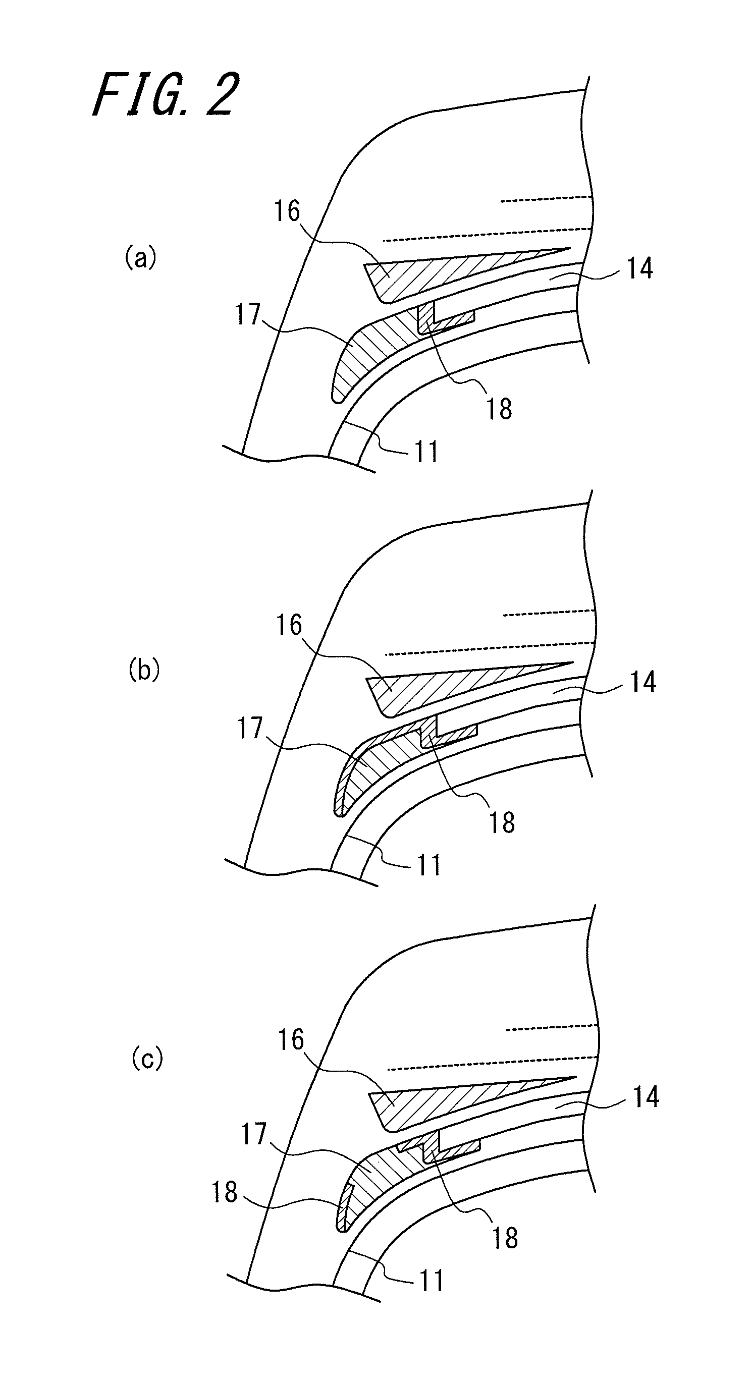
A belt width of an intersecting belt 15a having the maximum belt width is set to 80% or more of the maximum width of a carcass line; a difference in belt widths between the intersecting belt 15a and an intersecting belt 15b is set in the range of 10 mm to 50 mm on one side of the belt in the width direction; the intersecting belt 15a is not narrower than the circumferential belt 14, and the circumferential belt 14 is not narrower than the intersecting belt 15b; and a pneumatic tire according to the present invention has an interposed rubber 16 having a thickness increasing toward the widthwise outer side of the tire to be 3 mm or more, and a side-lower rubber 17 having an elastic modulus less than the elastic modulus of a coating rubber coating the circumferential belt 14.

Description

TECHNICAL FIELD[0001]The present invention relates to a pneumatic tire, and in particular, to a pneumatic radial tire for heavy loads employing a circumferential belt and favorably applied to trucks and buses.RELATED ART[0002]Conventionally, there have been known ultralow profile radial tires for trucks and buses (truck and bus radial tire: TBR) or other pneumatic radial tires for heavy load employing a circumferential belt located radially outward of the carcass of the tire and embedded in the tire along the tire circumferential direction in a layered manner.[0003]In recent years, large-sized trucks and buses increasingly employ a single-tire mounting configuration to reduce the fuel consumption and the weight of the vehicle. With the increase in the large-sized trucks and buses having the single-tire mounting configuration, the profiles of the tires have become lower, and tread bases of the tires have become wider. In general, pneumatic tires having the lower profile are configure...

Claims


Application Information

Patent Timeline
IPC IPC(8): B60C9/18
CPCY10T152/10801Y10T152/10765B60C9/18B60C9/28Y10T152/1081B60C2009/1842B60C2009/2064
Inventor NAKATA, HIROSHIMINOWA, HIDEAKI
Owner BRIDGESTONE CORP
Why Eureka
Try Eureka