
Tire assembly having an improved bead and a mounting rim

a technology of tire assembly and bead, which is applied in the direction of tire beads, tyre sidewalls, vehicle components, etc., can solve the problems of significant hysteresis losses, greenhouse gas emissions, and impact on vehicle fuel consumption, and achieves low rolling resistance and good endurance

Active Publication Date: 2015-01-22
MICHELIN & CO CIE GEN DES ESTAB MICHELIN +1
View PDF1 Cites 4 Cited by
  • Summary
  • Abstract
  • Description
  • Claims
  • Application Information

AI Technical Summary

Benefits of technology

This patent is about a new tire design for passenger cars that has low rolling resistance and good durability. The invention achieves this by reducing the compression and shear experienced by the rubber near the reinforcing elements in the tire. This is achieved by reducing the volume of the filler, which is traditionally made of a rubber with high hysteresis and causes energy dissipation when compressed. By maintaining the cornering stiffness and using a decoupling ply, the tire can provide better durability while still maintaining low rolling resistance.

Problems solved by technology

Reducing the emissions of greenhouse gases in the field of transport is one of the major challenges facing vehicle manufacturers today.
A great deal of progress has been made through tires, by lowering the rolling resistance, because this has a direct impact on vehicle fuel consumption.
The downside of this geometry is significant hysteresis losses, particular in the filler.
The stiffening action of the filler is applied especially in the region remote from the bead and therefore entails a filler that is even bulkier and, therefore, even greater hysteresis losses.
That tire, although it allows an excellent compromise between rolling resistance and cornering stiffness, has not lived up to expectations in terms of endurance.
When the filler is deformed, it therefore dissipates a great deal of energy.

Method used


Image

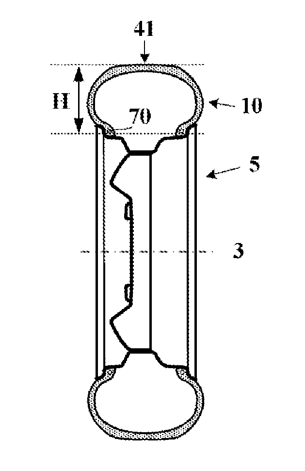
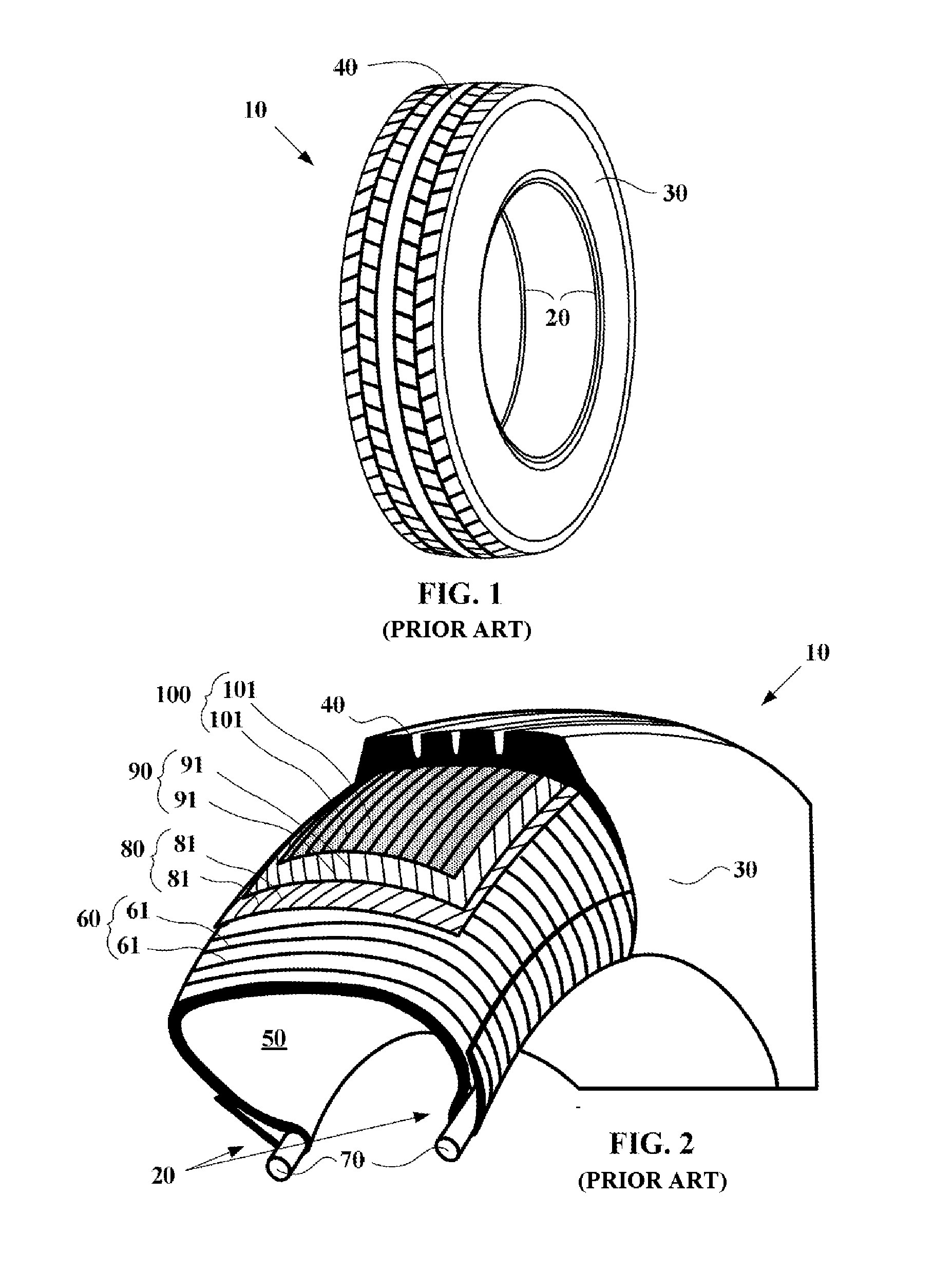
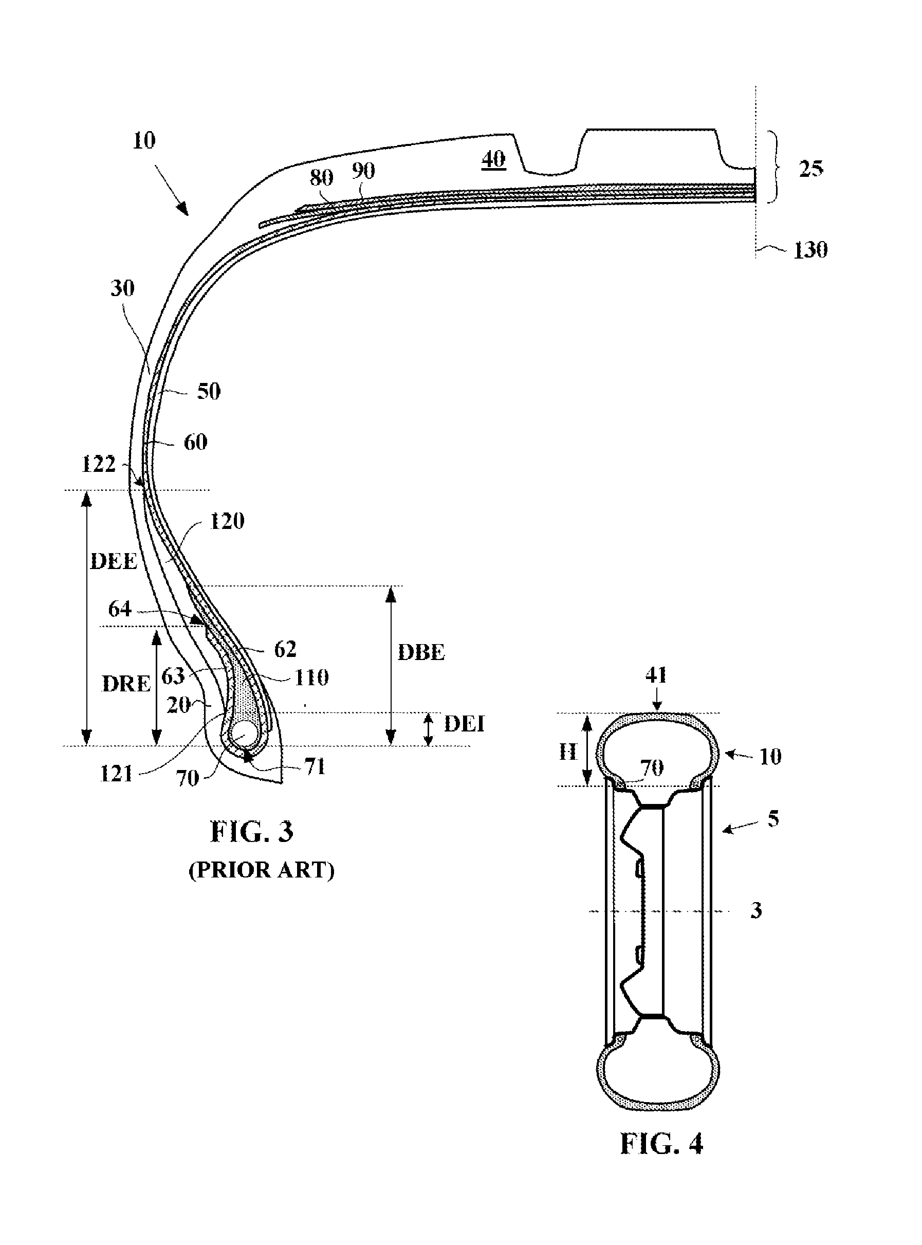
  • Tire assembly having an improved bead and a mounting rim
  • Tire assembly having an improved bead and a mounting rim
  • Tire assembly having an improved bead and a mounting rim

Examples


Embodiment Construction

[0047]When using the term “radial” it is appropriate to make a distinction between the various different uses made of this word by those skilled in the art. Firstly, the expression refers to a radius of the tire. It is in this sense that a point P1 is said to be “radially inside” a point P2 (or “radially on the inside of” the point P2) if it is closer to the axis of rotation of the tire than is the point P2. Conversely, a point P3 is said to be “radially outside” a point P4 (or “radially on the outside of” the point P4) if it is further away from the axis of rotation of the tire than is the point P4. Progress will be said to be “radially inwards (or outwards)” when it is in the direction towards smaller (or larger) radii. It is this sense of the term that applies also when matters of radial distance are being discussed.

[0048]By contrast, a thread or reinforcement is said to be “radial” when the thread or the reinforcing elements of the reinforcement make an angle greater than or equ...


PUM

PropertyMeasurementUnit
Fractionaaaaaaaaaa
Fractionaaaaaaaaaa
Fractionaaaaaaaaaa

Abstract

Assembly comprising a tire and a mounting rim, the tire comprising two beads each comprising at least one annular reinforcing structure and a carcass reinforcement anchored in the two beads by a turn-up, each bead comprising a filler of a rubber composition extending radially a radial distance DBE from the radially innermost point of the annular reinforcing structure, DBE being less than or equal to 10% of the radial height H of the tire, at least one sidewall further comprising a stiffening reinforcement of metallic reinforcing elements oriented at an angle less than or equal to 10 degrees to the circumferential direction, and positioned such that the distance DAE between the radially innermost point of the annular reinforcing structure and the radially outer end of the stiffening reinforcement is greater than or equal to 20% and less than or equal to 40% of H and that the distance DAI between the radially inner point of the annular reinforcing structure and the radially inner end of the stiffening reinforcement is less than or equal to 20% of H.

Description

[0001]This application is a 371 national phase entry of PCT / EP2013 / 053405, filed 21 Feb. 2013, which claims benefit of FR 1251787, filed 28 Feb. 2012, the entire contents of which are incorporated herein by reference for all purposes.BACKGROUND[0002]1. Field[0003]The present disclosure relates to tires for passenger vehicles, and notably the beads of these tires.[0004]2. Description of Related Art[0005]Reducing the emissions of greenhouse gases in the field of transport is one of the major challenges facing vehicle manufacturers today. A great deal of progress has been made through tires, by lowering the rolling resistance, because this has a direct impact on vehicle fuel consumption. Notable progress has been achieved and the great success of the Energy™ Saver tire recently marketed by Michelin for example bears witness to this. The technology employed allows around 0.2 l of fuel to be saved per 100 km in mixed cycle, representing a reduction of almost 4 g of CO2 per km. Over the l...

Claims


Application Information

Patent Timeline
IPC IPC(8): B60C9/02B60C9/00B60C13/00B60C15/06
CPCB60C13/00B60C9/02B60C2015/061B60C9/0007B60C15/0603B60C9/28B60C2015/0685B60C15/06B60C2015/0657B60C2015/0639B60C15/0628
Inventor BOURGEOIS, FREDERIC
Owner MICHELIN & CO CIE GEN DES ESTAB MICHELIN
Learn More