Steel production facility

A technology for production equipment and steel, applied in the field of shredded scrap iron, to save energy costs, shorten the period of iron tapping, and avoid system disturbances

Active Publication Date: 2012-05-02
拉斐克·布洛斯·道
View PDF14 Cites 6 Cited by
  • Summary
  • Abstract
  • Description
  • Claims
  • Application Information

AI Technical Summary

Problems solved by technology

For this, complex measurement and control mechanisms must be provided
In addition, for the stabilization of the exhaust gas temperature, the use of gas burners has the disadvantage of a major additional use of energy and the costs involved in it

Method used


Image

  • Steel production facility
  • Steel production facility
  • Steel production facility

Examples


Embodiment Construction

[0133] In the following description of the preferred embodiments of the present invention, like reference numerals refer to identical or comparable components.

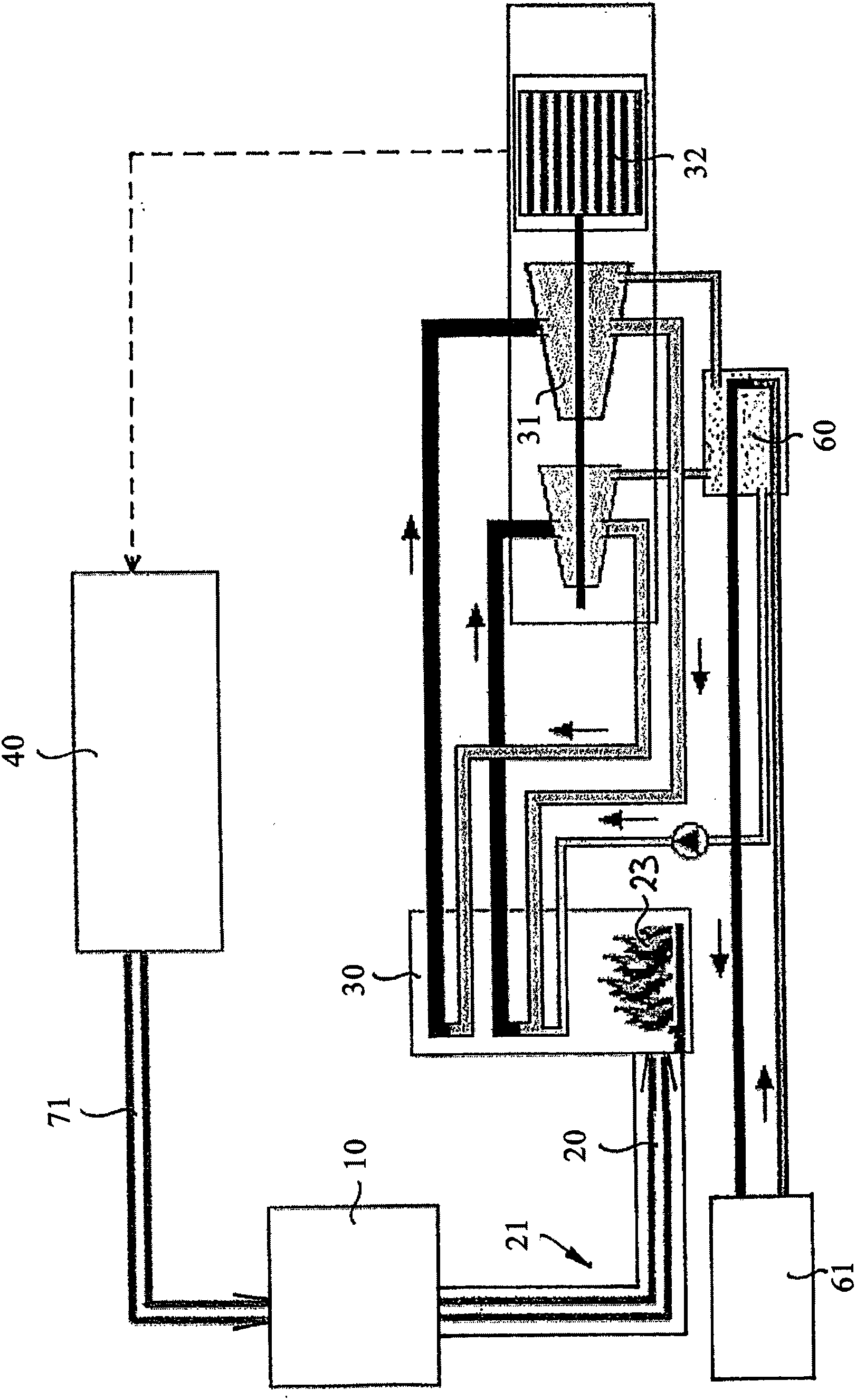
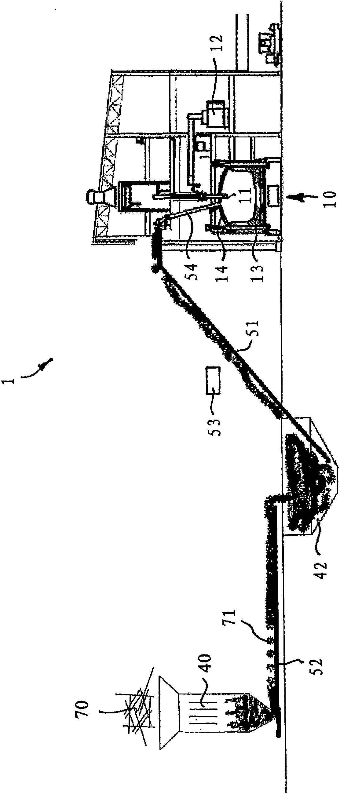
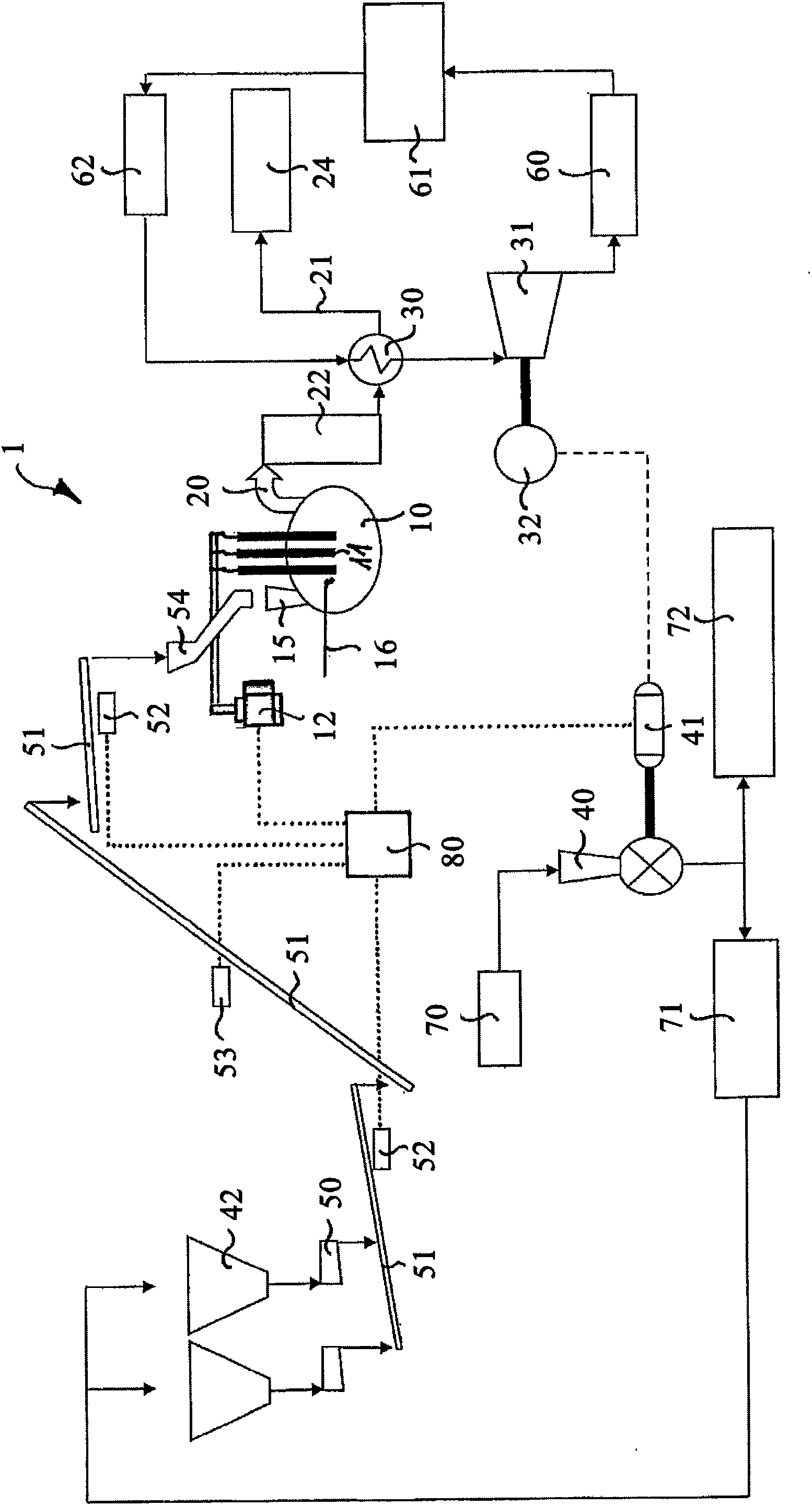
[0134] Reference is now made to these drawings in detail Figures 1 to 6 , and first refer to its figure 1 , is shown here by way of example a possible embodiment of a power generation mechanism that uses thermal energy contained in the thermal process exhaust gas (roof) 20 of an electric arc furnace 10 of a steel production facility for use in A shredding system 40 attached to the electric arc furnace (EAF) 10 is operated.

[0135] For this, at least a recuperator boiler 30 is installed in the exhaust gas system 21 of the dedusting plant 24 of the electric arc furnace 10 . The recuperator boiler 30 can be located in particular in the outlet of a settling tank 22 used in the exhaust gas 20 and / or in the area 23 of the exhaust gas system 21 , or to the preceding equipment 22 / Dust particles contained in the seconda...


PUM


Abstract

The present invention relates to a steel production facility (1) and a method of uninterrupted or at least cyclical steelmaking in said facility (1), wherein in case of uninterrupted steelmaking at least the first three of the following steps and in case of cyclical steelmaking all five steps will be used: charge materials are molten uninterruptedly or at least cyclically in an electric arc furnace (10); the charge materials like in particular shredded scrap-iron pieces (71) shredded in a shredding-system (40) for shredding discarded iron and/or steel junk (scrap 70), Direct Reduced Iron (DRI) and/or Hot Briquette Iron (HBI) are uninter- ruptedly or at least continuously during a melting process cycle fed into the electric arc furnace (10) by means of conveyance (50, 51,...); a part of liquid steel is uninterruptedly or cyclically discharged from the steel bath of the electric arc furnace (10); from the thermic energy included in the hot process-exhaust (furnace top 20) of the electric arc furnace (10), electric energy is, by means of power generation (30, 31, 32), generated uninterruptedly or at least during a melting process cycle; a shredding-system (40) assigned to the electric arc furnace (10) for shredding discarded iron and/or steel junk (scrap 70) is powered uninterruptedly or at least during a melting process cycle by the electric energy generated from the process exhaust (furnace top 20). The present steel production facility (1), which sets new standards in terms of total energy-balance with regard to productivity and energy saving, consistently continues the trend of the last years.

Description

technical field [0001] The present invention relates to a steel production plant and a method for uninterrupted or at least cyclical steelmaking in the plant, the plant comprising at least an electric arc furnace (EAF) for uninterrupted or at least cyclical melting of load material, Especially like shredded scrap iron. Background technique [0002] In one aspect, steel can be made from iron ore and pig iron via the route of blast furnaces and reformers. However, with respect to energy efficiency, it is on the other hand more advantageous to produce steel mainly by melting scrap iron sheets in the electric arc furnace, which is still the most common loading material for electric arc furnaces throughout the world . [0003] Steelmaking in this Electric Arc Furnace (EAF): [0004] In the common electric arc furnace process, electrical and chemical energy is used to melt the load material cyclically back and forth. During this process, a substantial portion of the total ener...

Claims


Application Information

Patent Timeline
Patent Type & Authority Applications(China)
IPC IPC(8): F27B3/08F27B3/18F27B3/26F27D17/00C21C5/52
CPCF27B3/26C21C5/5294F27B3/18C21C5/527F27B3/085C21C2200/00C21C2005/5282F27D17/004Y02P10/20
Inventor 拉斐克·布洛斯·道
Owner 拉斐克·布洛斯·道
Why Eureka
Try Eureka