Measuring method for determining the position and the orientation of a moving assembly, and apparatus for implementing said method

a technology of moving assembly and measuring method, which is applied in the direction of electrical/magnetic measuring arrangement, color television, television system, etc., can solve the problems of high production cost of type of apparatus, unusable apparatus, heavy and bulky apparatus, etc., and achieve the effect of convenient transportation

Inactive Publication Date: 2003-10-28
HEXAGON TECH CENT GMBH
View PDF6 Cites 101 Cited by
  • Summary
  • Abstract
  • Description
  • Claims
  • Application Information

AI Technical Summary

Benefits of technology

The images of the optical reference marks make it possible to determine relative rotation between the two optical reference marks and also relative offset between the two optical reference marks in a plane normal to the focal axis of the first camera. Distance measurement makes it possible to determine the distance between the two optical reference marks, and to do so very accurately because of the self-contained nature of the measurement means used which does not depend on the cameras, unlike the previously known methods outlined above.
Also advantageously, the second assembly can be detachably received by the first assembly. This makes the apparatus easier to transport. Similarly, the computer is advantageously carried by the first assembly.

Problems solved by technology

That type of apparatus is transportable, but it is sometimes heavy and bulky, and even when folded the arm projects considerably from the base.
Furthermore, when deployed, the arm is fragile and can be twisted during clumsy handling, thereby completely falsifying any determination of the orientation of the end support or of the position of the feeler ball, thus making the apparatus unusable.
Finally, the presence of numerous mechanical parts and high precision hinges makes that type of apparatus expensive to produce.
The major drawback of those methods lies in the lack of accuracy with which distances are measured by analyzing images, which puts a de facto limit on the accuracy with which precision can be identified.

Method used


Image

  • Measuring method for determining the position and the orientation of a moving assembly, and apparatus for implementing said method
  • Measuring method for determining the position and the orientation of a moving assembly, and apparatus for implementing said method
  • Measuring method for determining the position and the orientation of a moving assembly, and apparatus for implementing said method

Examples


Embodiment Construction

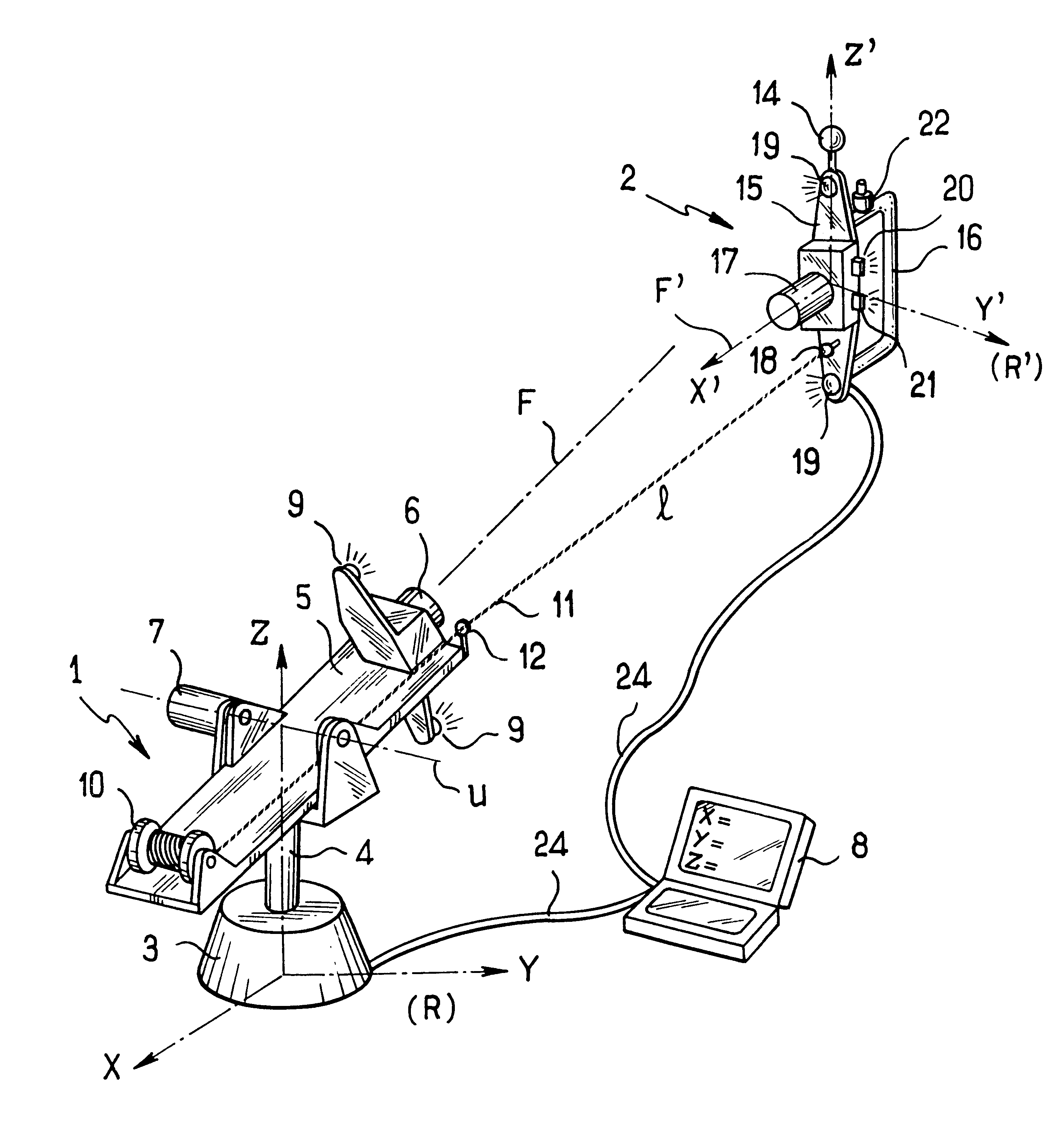
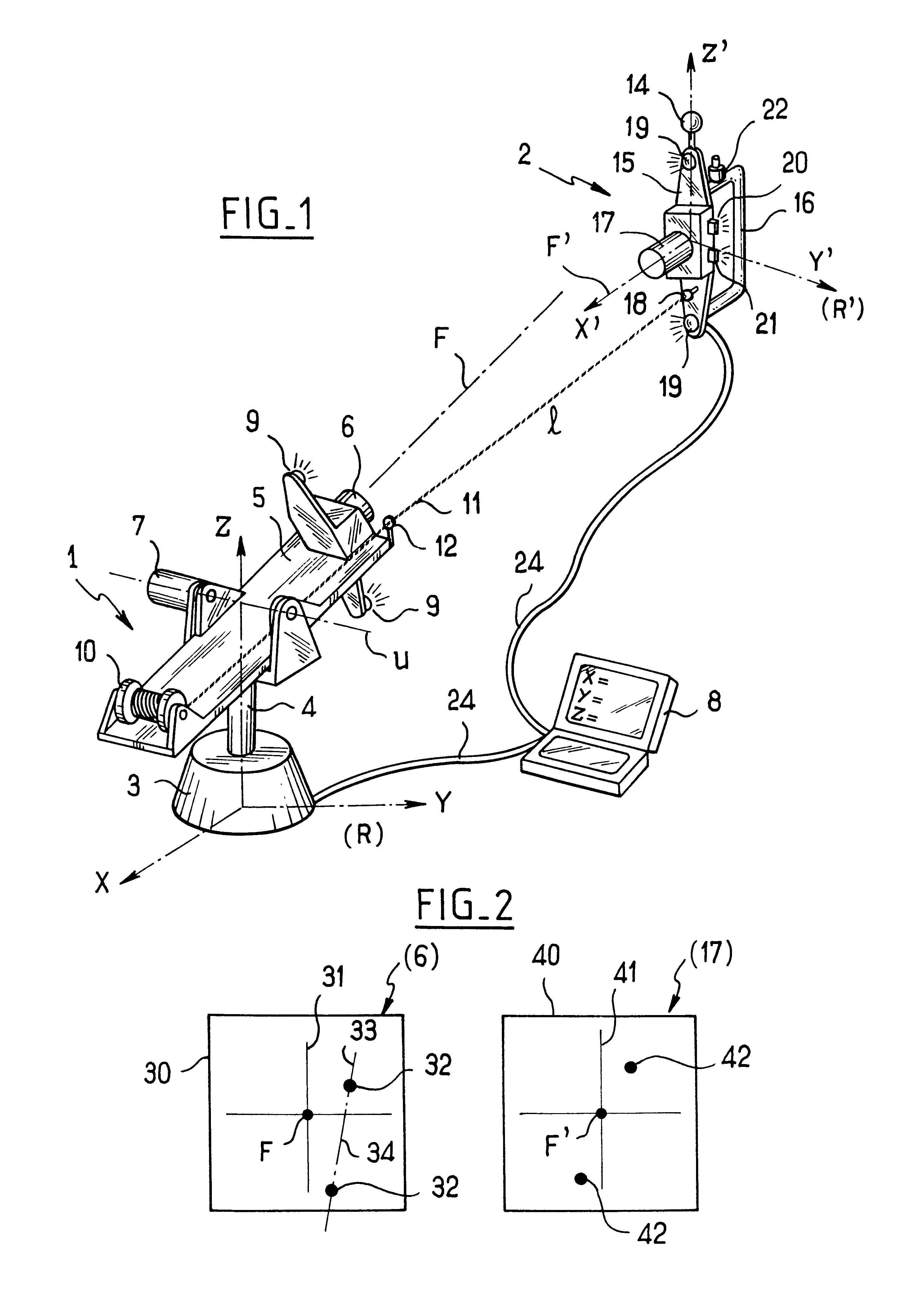
With reference to FIG. 1, measurement apparatus of the invention comprises a first assembly or base 1 and a second or "moving" assembly 2.

The base 1 comprises a stand 3 standing on the ground and carrying a fork 4 which is mounted to rotate about a vertical Z-axis. An encoder (not visible in the drawing) serves to measure the angular position of the fork 4 about the Z-axis, taking as its origin an X-axis perpendicular to the Z-axis and of orientation that is fixed relative to the stand 3.

A Y-axis perpendicular both to the X-axis and to the Z-axis serves to define a frame of reference R referred to as the "base" frame of reference.

The fork 4 carries a cradle 5 hinged to the fork about an axis U contained in a plane that is normal to the Z-axis. Tilting of the cradle about the axis U is measured using an associated encoder 7.

The cradle 5 also carries a first camera 6 defining a focal axis F. By measuring both turning of the cradle 5 about the Z-axis and tilting of the cradle about the...


PUM


Abstract

The invention relates to a measurement method for determining the position and the orientation of a moving assembly in a base frame of reference. According to the invention, the method comprises the steps of: taking an image of an optical reference mark associated with the moving assembly by means of a first camera having a focal axis lying in a direction that is known in the base frame of reference; taking an image of an optical reference mark associated with the first camera by means of a second camera associated with the moving assembly; measuring the distance between a point associated with the first camera and a point associated with the second camera by using self-contained measurement means that are independent of said first and second cameras; and computing the position and the orientation of the moving assembly in the base frame of reference on the basis of the images taken and of the measured distance.

Description

This application is entitled to the benefit of and incorporates by reference essential subject matter disclosed in French Patent Application No. 01 05484 filed on Apr. 24, 2001.The invention relates in particular to apparatus for use in vehicle body building to measure deformations or to verify that bodywork assemblies are properly positioned relative to the remainder of a structure.In this field, measurement devices are known of the type comprising a base having a hinged arm connected thereto, the arm having an end support carrying a feeler ball.Each hinge of the arm is fitted with an encoder, so that it suffices to collect the measurements from each of the encoders in order to determine the orientation of the end support and the position of the feeler ball in a frame of reference associated with the base.That type of apparatus is transportable, but it is sometimes heavy and bulky, and even when folded the arm projects considerably from the base.Furthermore, when deployed, the arm ...

Claims


Application Information

Patent Timeline
Patent Type & Authority Patents(United States)
IPC IPC(8): G01B11/00
CPCG01B11/002
Inventor GRANGER, ROMAIN
Owner HEXAGON TECH CENT GMBH
Why Eureka
Try Eureka