Aircraft passenger seat frame construction

a passenger seat and frame technology, applied in the direction of seat arrangement, emergency apparatus, pedestrian/occupant safety arrangement, etc., can solve the problems of waste, prior art design waste, and inefficiency, and achieve the effect of reducing the diameter of the beam collar

Inactive Publication Date: 2003-11-11
BE AEROSPACE INCORPORATED
View PDF7 Cites 45 Cited by
  • Summary
  • Abstract
  • Description
  • Claims
  • Application Information

AI Technical Summary

Benefits of technology

It is another object of the invention to provide a passenger seat frame assembly which eliminates or reduces the need to drill attachment holes in beam elements specific to particular seat configurations and spacings.
Because the latch 160 captures the meal tray 151 through the latch access port 153, inadvertent disengagement of the meal tray 151 by force applied in any direction is prevented, in contrast with current "barn door" latches. In addition, the recess 154 around the latch access port 153 prevents inadvertent rotation of the latch 160 and deployment of the meal tray 151 to the use position, as might otherwise occur when a passenger brushes against the tray while moving to or from his or her own seat.

Problems solved by technology

Many of these parts are fabricated for a specific location by the placement of holes in the components to attach them together, rendering them unusable in other positions within the aircraft.
Prior art designs thus produce waste and inefficiency.

Method used


Image

  • Aircraft passenger seat frame construction
  • Aircraft passenger seat frame construction
  • Aircraft passenger seat frame construction

Examples


Embodiment Construction

Seat Assembly Overview

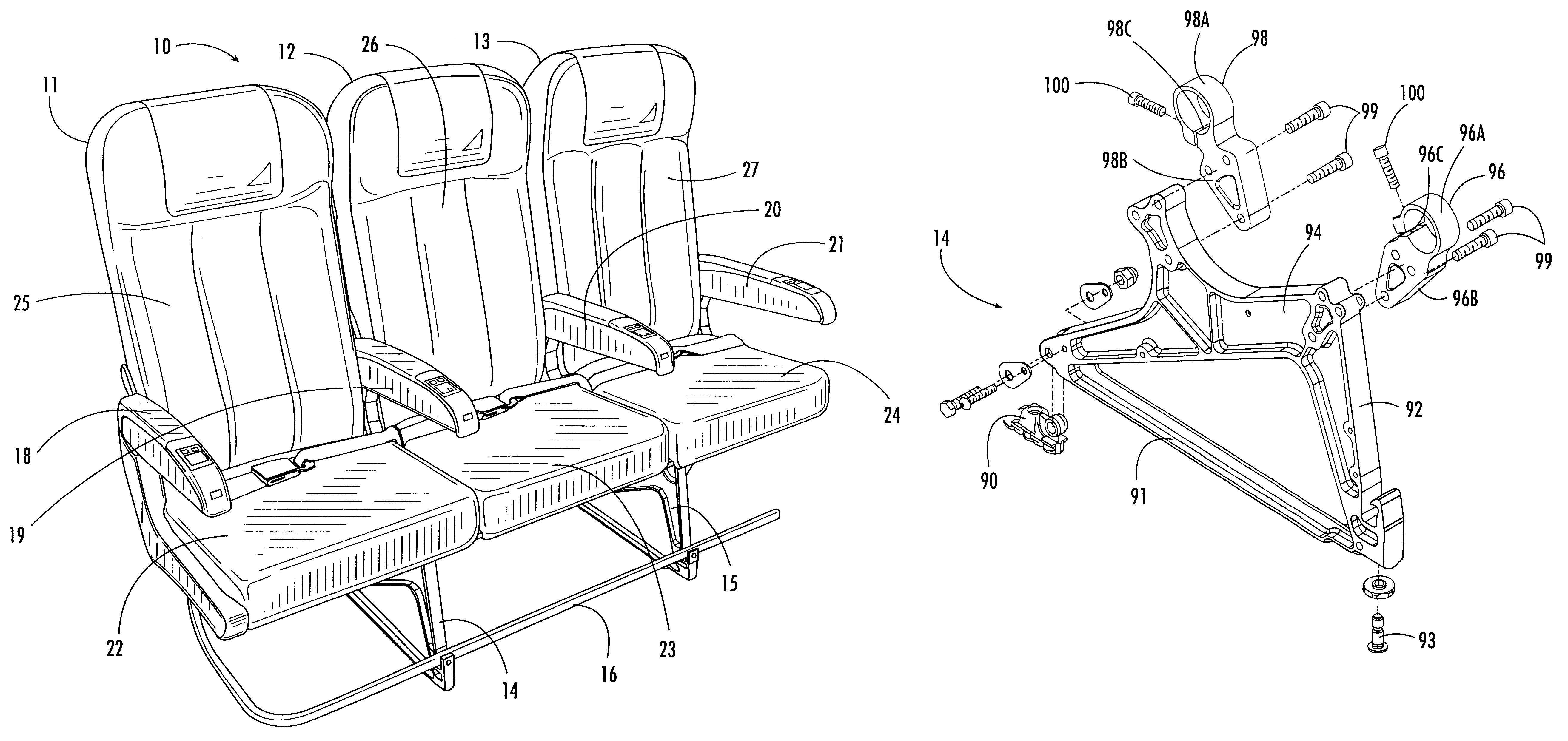
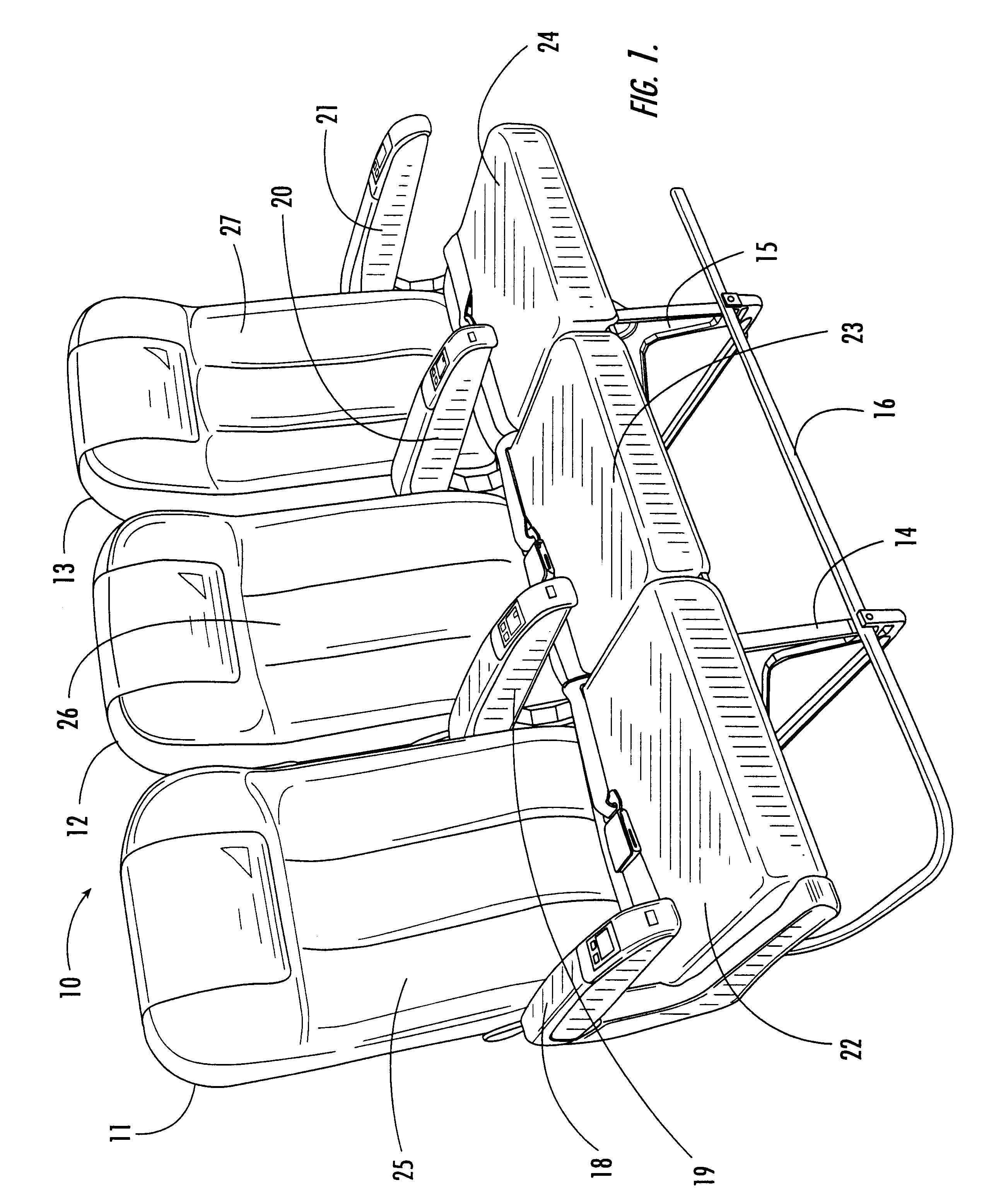
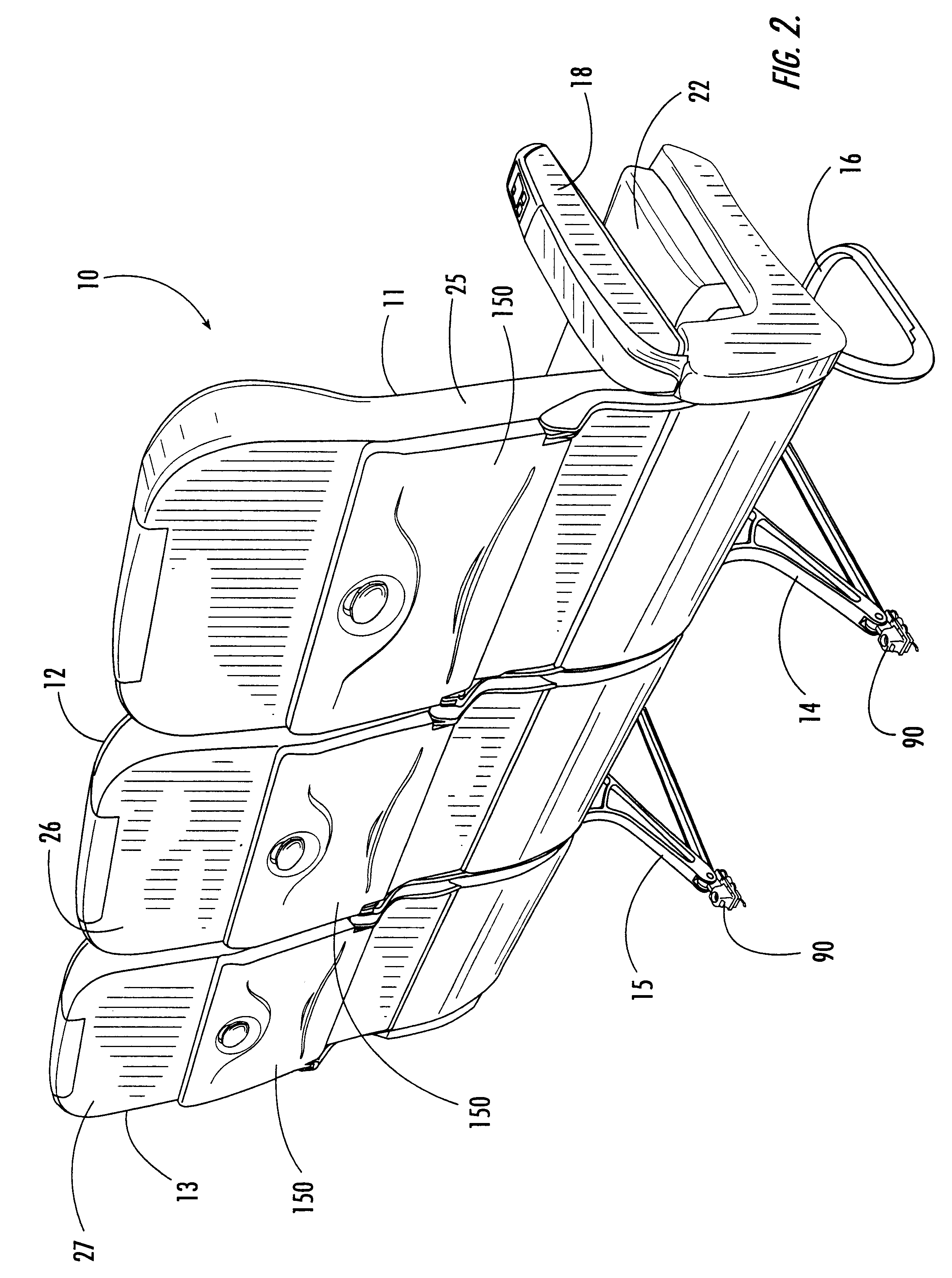
Referring now specifically to the drawings, an aircraft passenger seat set according to the present invention is illustrated in FIGS. 1, 2 and 3 and shown generally at reference numeral 10. In the particular embodiment shown in FIGS. 1, 2 and 3, the seat set 10 is comprised of three adjacent seats, an aisle seat 11, a center seat 12 and a window seat 13. The seat set 10 is supported on a pair of leg modules 14 and 15, and includes a baggage guard rail 16. The seats 11, 12 and 13 are provided with arm rests 18, 19, 20 and 21. The seats 11, 12 and 13 include seat bottoms 22, 23 and 24, respectively, and seat backs 25, 26 and 27, respectively.

The internal structure of the seat set is shown in FIG. 4, with various parts eliminated for clarity. As is shown, the seat set 10 is supported on and thus shares the two leg modules 14 and 15. The leg modules 14 and 15 carry a set of four laterally-extending beam elements 35, 36, 37 and 38 on which are mounted four section a...


PUM


Abstract

A passenger seat frame assembly, including a seat bottom chassis including a plurality of leg modules and section assembly modules. The leg modules are attached to fixed, spaced-apart attachment points on a supporting surface, such as the deck of an aircraft fuselage. A plurality of beam elements are carried by the leg modules and section assembly modules. A plurality of clamp joints are provided for being positioned on the plurality of leg modules and for receiving the plurality of beam elements in spaced-apart relation to each other for defining a ladder frame assembly having a specified width and seat spacing.

Description

TECHNICAL FIELD AND BACKGROUND OF THE INVENTIONThis invention relates to a seat frame construction, particularly one for use with an aircraft passenger seat. Aircraft passenger seats are constructed from modular components, the size, weight and construction of which are dictated by many considerations, including fuselage dimensions, aesthetic and safety considerations. Many of these requirements are imposed by law or regulation. The lower seat chassis is constructed of leg modules, while the upper seat is constructed of section assembly modules. In prior art seating systems the leg modules and section assembly modules are connected by mounting both to a series of parallel beams which extend laterally from one side of the seat or seat assembly to the other.The location of the upper seat section modules is controlled by the aircraft fuselage lines, statutory aisle requirements and carrier preferences within these parameters. The location of the leg modules is governed by the positions...

Claims


Application Information

Patent Timeline
Patent Type & Authority Patents(United States)
IPC IPC(8): B60N2/68B64D11/06B64D11/00
CPCB60N2/682B64D11/06B64D11/064B64D11/0638Y02T50/46B64D11/0648B64D11/0696B64D11/0649Y02T50/40B64D11/0647
Inventor WILLIAMSON, JOHN
Owner BE AEROSPACE INCORPORATED
Why Eureka
Try Eureka