Fuel injector
a fuel injector and injector technology, applied in the direction of combustion types, machines/engines, lighting and heating apparatus, etc., can solve the problems of affecting the generation of combustion vibration, destroying components, and affecting the vibration behavior of combustion,
- Summary
- Abstract
- Description
- Claims
- Application Information
AI Technical Summary
Benefits of technology
Problems solved by technology
Method used
Image

Examples
Embodiment Construction
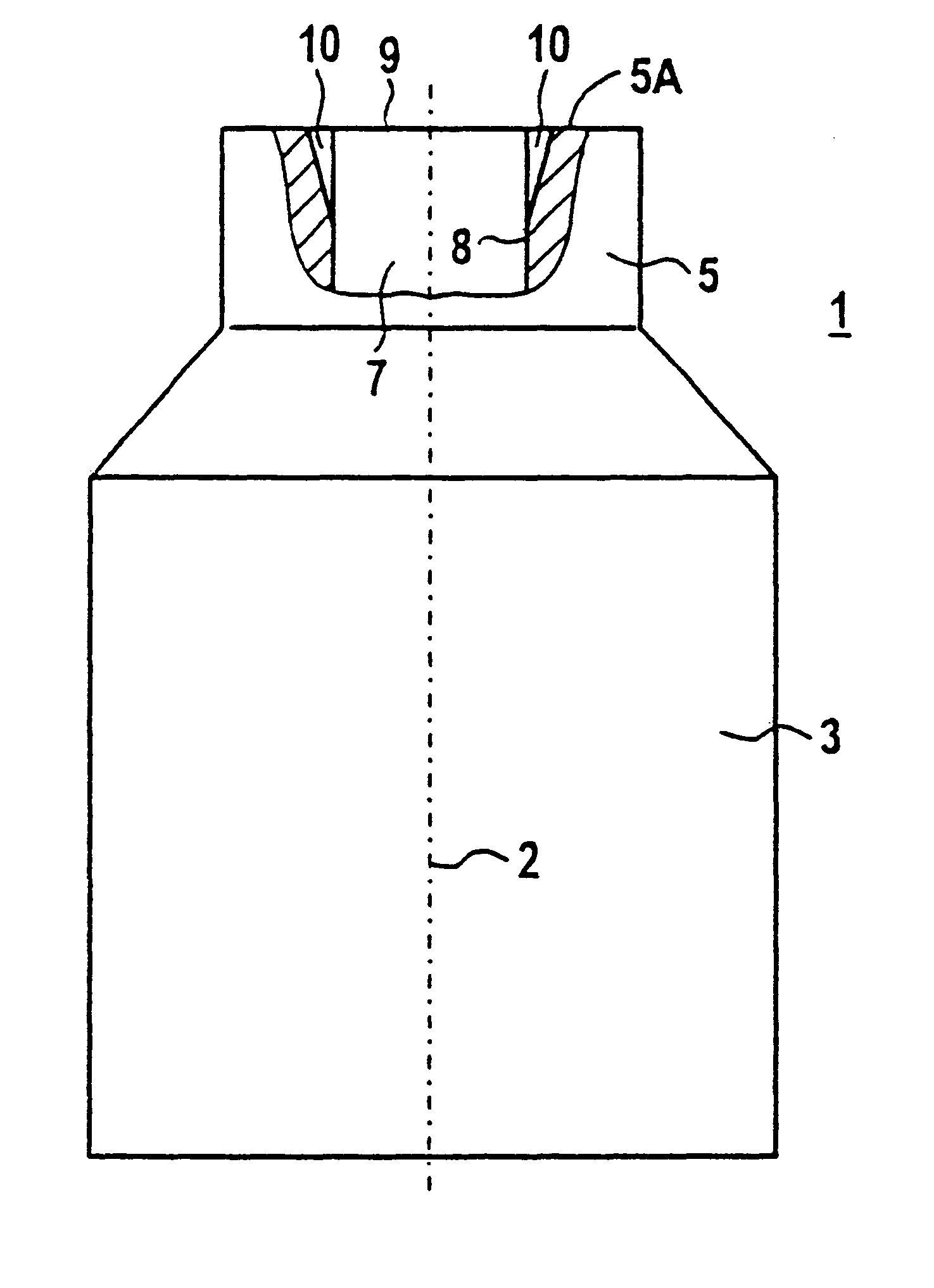
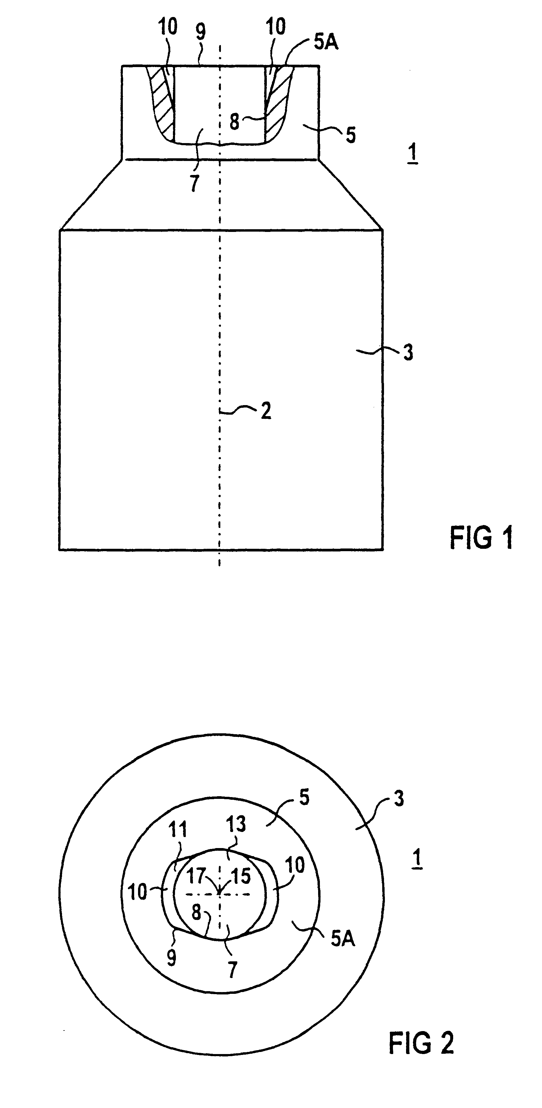
FIG. 1 shows the side view of a fuel injector 1. A cylindrical injector body 3 narrows in a frustoconical section to a likewise cylindrical orifice region 5 having an end face 5A. Directed along an injector axis 2, an orifice passage 7 runs in the fuel injector 1 and opens at the end of the orifice region 5 with an orifice edge 9. The orifice region 5 is sectioned at right angles so that a bevel 10 of the passage wall 8 of the orifice passage 7 can be seen. Due to this bevel 10, the orifice 30 edge 9 is rotationally asymmetrical about the injector axis 2. This becomes clear in FIG. 2.
FIG. 2 shows a plan view of the fuel injector 1 from FIG. 1. The orifice edge 9 is given twofold symmetry by two bevels 10 of the passage wall 8 located opposite one another. The orifice edge 9 therefore corresponds to a contour which is formed by the outer edge of a rectangle 11 and a circle 13, the circle 13 lying with its center 15 on the centroid 17 of the rectangle 11 and extending beyond the narro...
PUM
 Abstract
Description
Claims
Application Information