Plastic container closure

a container and plastic technology, applied in the field of plastic container closures, can solve the problems of leakage of gas pressure inside the container, deformation of the annular seal piece, and increase of the manufacturing cost of the container closur

Inactive Publication Date: 2004-02-24
JAPAN CROWN CORK CO LTD
View PDF10 Cites 57 Cited by
  • Summary
  • Abstract
  • Description
  • Claims
  • Application Information

AI Technical Summary

Benefits of technology

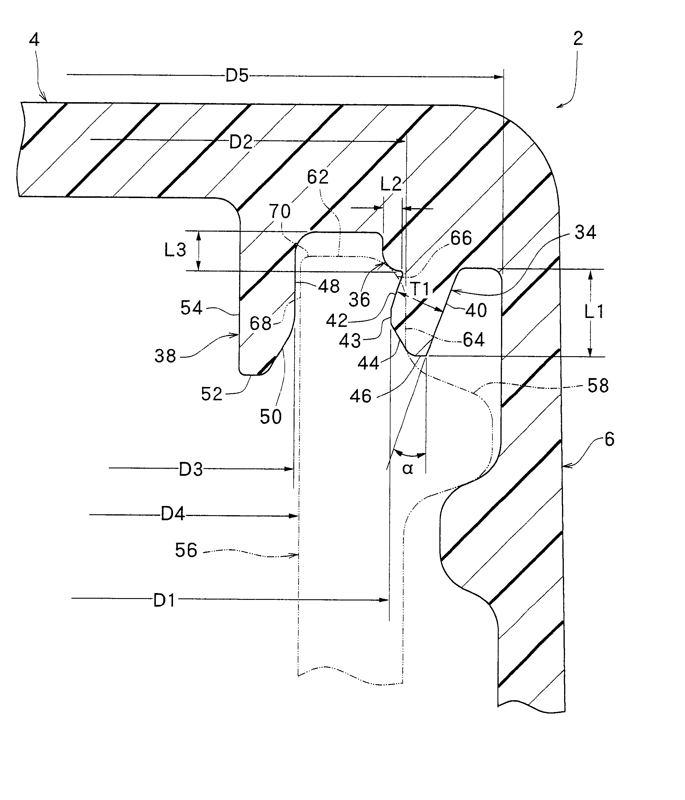
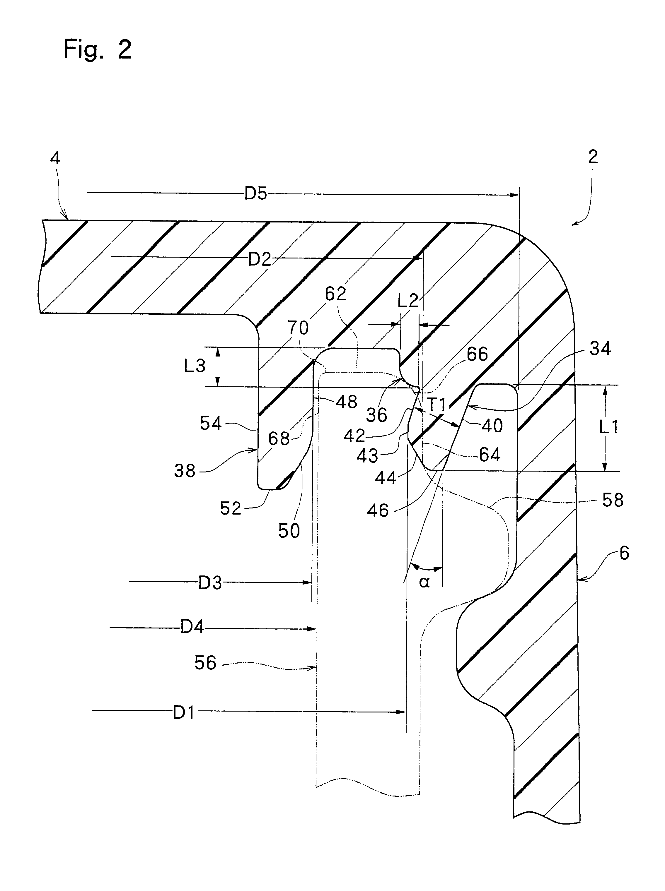
As a result of extensive studies and experiments, the inventors found the following facts, to their surprise: When the annular contact piece is changed to such a shape as to contact the annular boundary surface extending arcuately in the sectional view, rather than contacting the substantially horizontally extending top surface of the mouth-and-neck portion, sealing of the mouth-and-neck portion by the container closure can be maintained fully reliably, even if a considerably great stacking load is imposed on the top panel wall of the container closure when the above-mentioned dome phenomenon is caused to the top panel wall of the container closure. The reason why sealing of the mouth-and-neck portion can be maintained fully reliably by such a change applied to the annular contact piece of the container closure is not necessarily clear, but the inventors believe it to be as follows: Generally, when the dome phenomenon is caused to the top panel wall, the top panel wall is deformed upward in a region inward of the annular boundary surface of the mouth-and-neck portion. In other words, the top panel wall bulges upward more greatly in its region closer to its center, with the annular boundary surface of the mouth-and-neck portion as a fulcrum. If the annular contact piece of the container closure is in contact with the top surface inward of the annular boundary surface of the mouth-and-neck portion, the top panel wall is deformed, when a stacking load is imposed on the top panel wall undergoing the dome phenomenon. In accordance with this deformation, the annular contact piece is also deformed or moved. At the same time, the deformation of the top panel wall is transmitted to the annular seal piece. As a result, the annular seal piece is also deformed to destroy sealing of the mouth-and-neck portion. On the other hand, when the annular contact piece of the container closure is brought into contact with the annular boundary surface of the mouth-and-neck portion, namely, the fulcrum for the deformation of the top panel wall, the tendency toward the deformation or movement of the annular contact piece by the deformation of the top panel wall is considerably lessened. Moreover, the tendency to deformation of the annular seal piece due to the deformation of the top panel wall is considerably suppressed. Hence, the sealing of the mouth-and-neck portion is maintained.
The inventors further conducted extensive studies and experiments, and found the following facts: When an annular thin-walled region is formed radially inwardly of the annular seal piece in the top panel wall, deformation of the top panel wall (i.e., a dome-shaped deformation, or the dome-shaped deformation forcibly returned to the original state) is restricted mainly to a region inward of the annular thin-walled region, and deformation of the top panel wall in an area radially outward of the annular thin-walled region is fully suppressed. Thus, deformation or movement of the annular seal piece is fully suppressed. Consequently, even when a considerably great stacking load is imposed on the top panel wall of the container closure undergoing the dome phenomenon, sealing of the mouth-and-neck portion of the container by the container closure can be maintained fully reliably.

Problems solved by technology

According to experiments conducted by the inventors of the present invention, when a considerably great stacking load is imposed on the top panel wall of the container closure subject to the dome phenomenon, the seal on the mouth-and-neck portion by the container closure tends to be destroyed, resulting in leakage of the gas pressure from inside the container.
By so doing, however, the manufacturing cost of the container closure is considerably increased.
As a result, the annular seal piece is also deformed to destroy sealing of the mouth-and-neck portion.
If D2-D1 is too large, an operation of mounting the container closure on the mouth-and-neck portion 56 tends to become difficult.
If D4-D3 is too small, positioning the annular positioning piece 38 in the mouth-and-neck portion 56 when mounting the container closure on the mouth-and-neck portion of the container tends to become considerably difficult.

Method used


Image

  • Plastic container closure
  • Plastic container closure
  • Plastic container closure

Examples


example 2

There were produced 30 of the same container closures as in Example 1, except that the shape of the container closure was as shown in FIG. 4, and

The above container closure was subjected to the same stacking load resistance test as in Example 1. The results are shown in Table 1.

example 3

There were produced 30 of the same container closures as in Example 1, except that the shape of the container closure was as shown in FIG. 5, and

The above container closure was subjected to the same stacking load resistance test as in Example 1. The results are shown in Table 1.

example 4

There were produced 30 of the same container closures as in Example 1, except that the shape of the container closure was as shown in FIGS. 6 and 7, and

The above container closure was subjected to the same stacking load resistance test as in Example 1. The results are shown in Table 1.


PUM


Abstract

A container closure has a top panel wall, and an annular seal piece and an annular contact piece are integrally formed in an outer peripheral edge portion of an inner surface of the top panel wall. The annular seal piece is of such a shape as to be deflected radially outwardly upon contact with the cylindrical outer peripheral surface of the mouth-and-neck portion of a container. The annular contact piece is brought into contact with an annular boundary surface extending from an annular top surface to an annular outer peripheral surface of the mouth-and-neck portion of the container when viewed arcuately in a sectional view. An annular thin-walled region positioned radially inwardly of the annular seal piece and the annular contact piece are further formed in the outer peripheral edge portion of the inner surface of the top panel wall.

Description

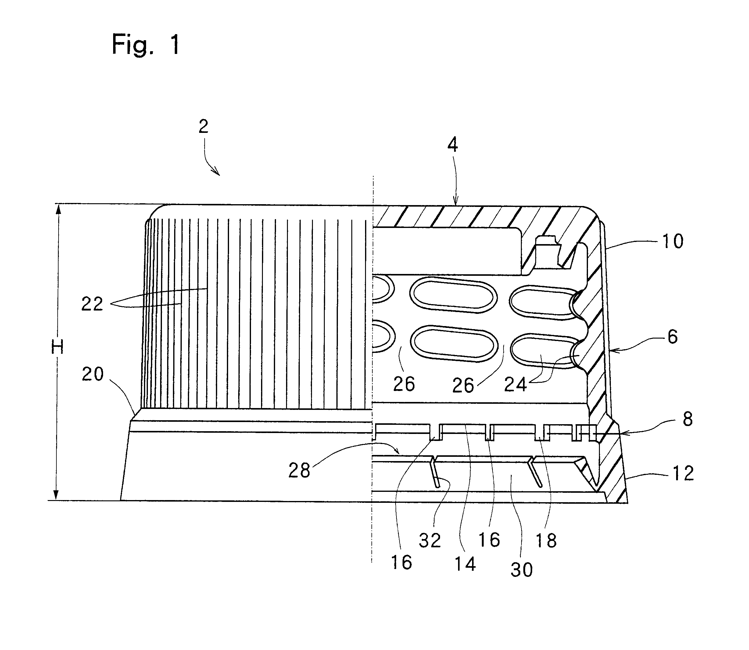
This invention relates to a plastic container closure suitable for a container for a beverage, especially a container for a carbonated beverage.DESCRIPTION OF THE PRIOR ARTA container formed from a plastic material, such as polyethylene terephthalate or glass, is widely used as a container for a beverage. Such a container includes a nearly cylindrical mouth-and-neck portion, and an external thread is formed on an outer peripheral surface of the mouth-and-neck portion. An upper end part of the mouth-and-neck portion, normally positioned above the external thread, has an annular top surface extending substantially horizontally, a cylindrical outer peripheral surface extending substantially vertically, and a cylindrical inner peripheral surface extending substantially vertically. The annular top surface and the cylindrical inner peripheral surface are connected together, substantially directly or via an annular boundary surface extending arcuately over a slight length in a sectional vi...

Claims


Application Information

Patent Timeline
Patent Type & Authority Patents(United States)
IPC IPC(8): B65D41/34
CPCB65D41/0421B65D41/3428Y10S215/01
Inventor KANO, YUJIKAITSUKA, YOSHIHIRO
Owner JAPAN CROWN CORK CO LTD
Why Eureka
Try Eureka