Neck-slip-prosthesis

a technology of prosthesis and neck, applied in the field of neck prosthesis, can solve the problems of bone atrophy and resorption, and the problem of not being remedied, and achieve the effect of improving the quality of li

Inactive Publication Date: 2004-03-16
THURGAUER KANTONALBANK A CHARTERED IN & EXISTING UNDER THE LAWS OF SWITZERLAND THAT MAINTAINS ITS PRINCIPAL OFFICES AT
View PDF7 Cites 62 Cited by
  • Summary
  • Abstract
  • Description
  • Claims
  • Application Information

AI Technical Summary

Problems solved by technology

125, Berlin, Heidelberg, New York: Springer) However, the collar abutments and the rigid design led to bone atrophy and resorption, a clear indication that the transfer of force was not physiological.
The problem, moreover, was not remedied by using highly porous structures in the stem element.
However, it is precisely the internal structures of the femoral neck that do not allow straight stems or shafts to be anchored; these structures demand right-left opposite symmetry.

Method used


Image

  • Neck-slip-prosthesis
  • Neck-slip-prosthesis
  • Neck-slip-prosthesis

Examples


Embodiment Construction

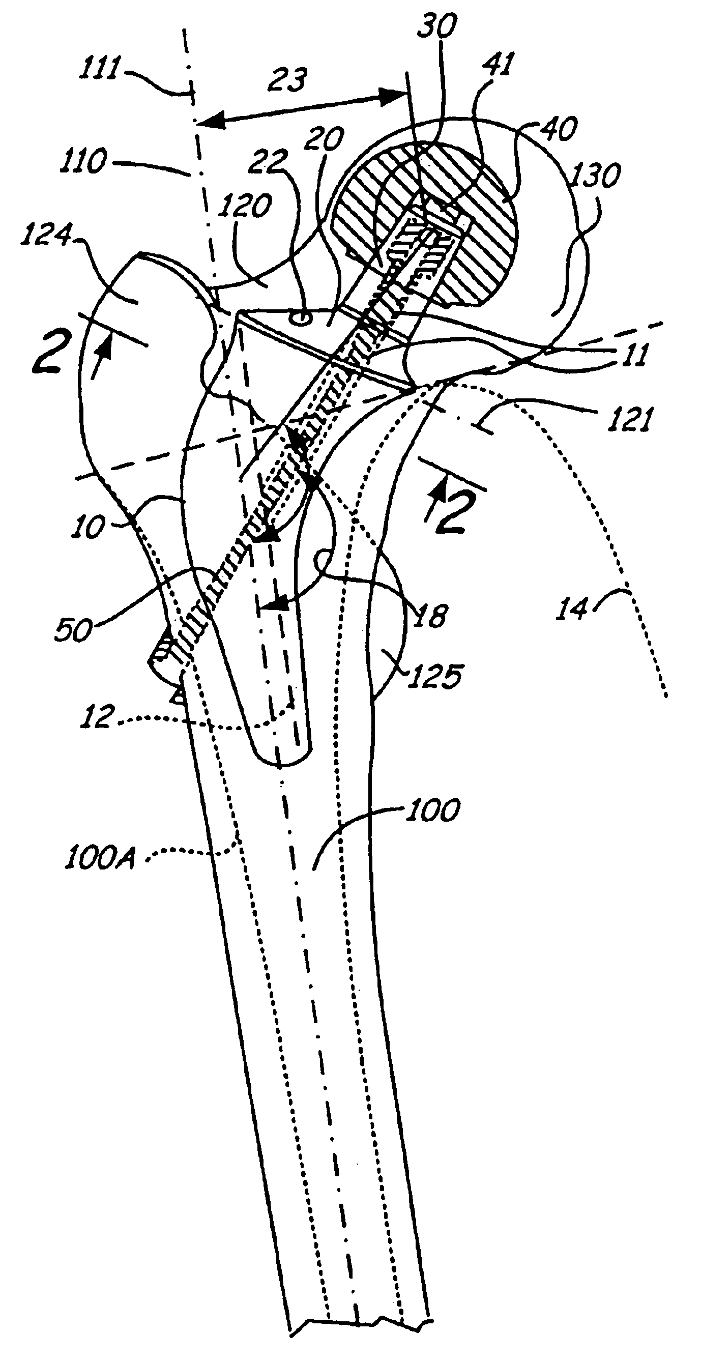
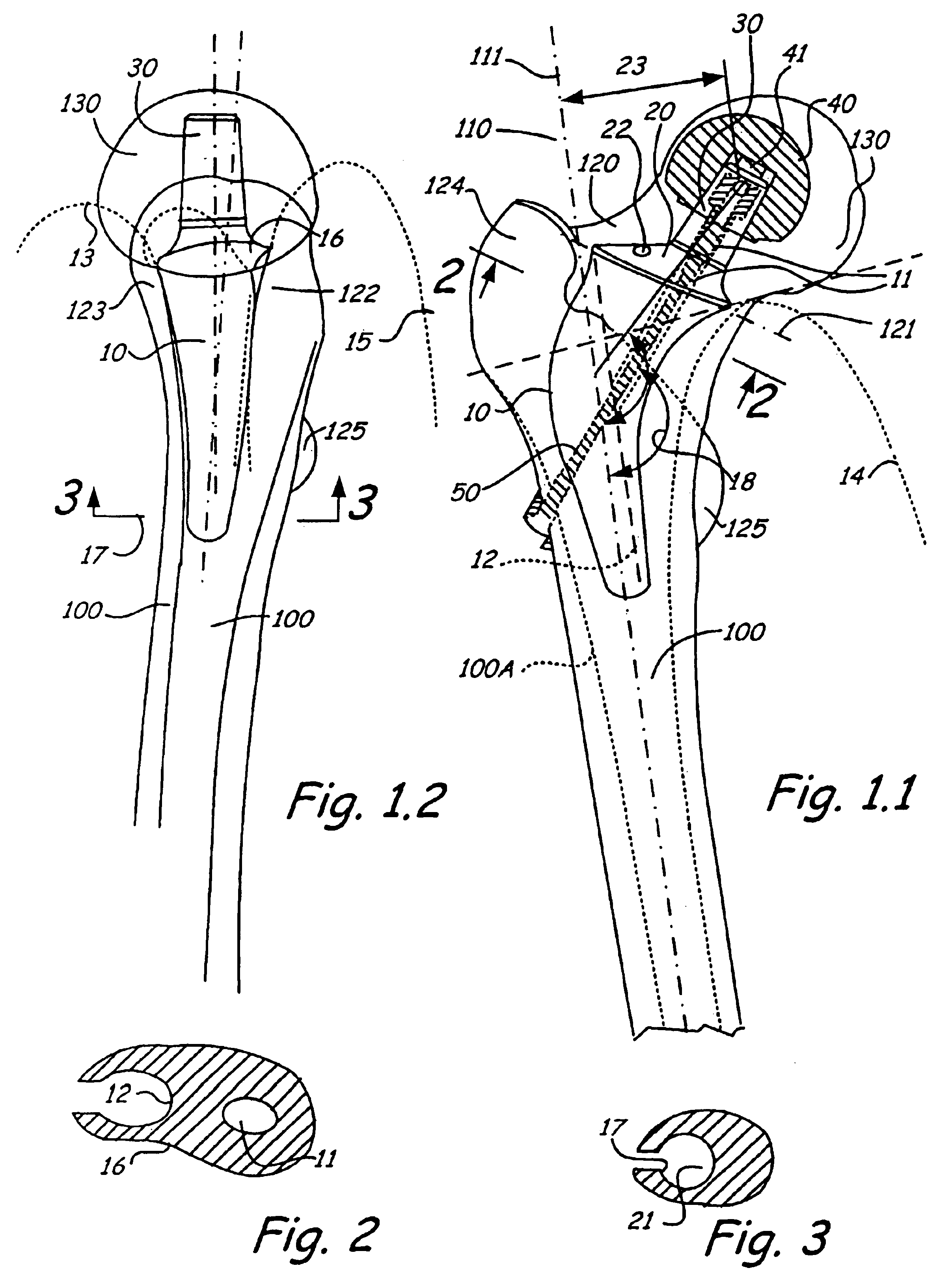
The hip joint is exposed, for example, using Bauer's methodology with the patient in the dorsal position. The dome is removed by an osteotomy along line or plane 121 in FIG. 1.1 and the femur is dislocated. The head of the femur is removed by separation along osteotomy line 121 while preserving the femoral neck 120. The head-end (cone 30) of the prosthesis is prepared. For example, a press-fit ceramic head implant, such as 40, is ground to shape and is inserted in the head or metaphysis 130. The femur is then rotated outward and adduced, and the intermedullary canal of the femur 100 is opened up using an 11.2-mm diamond grinding wheel.

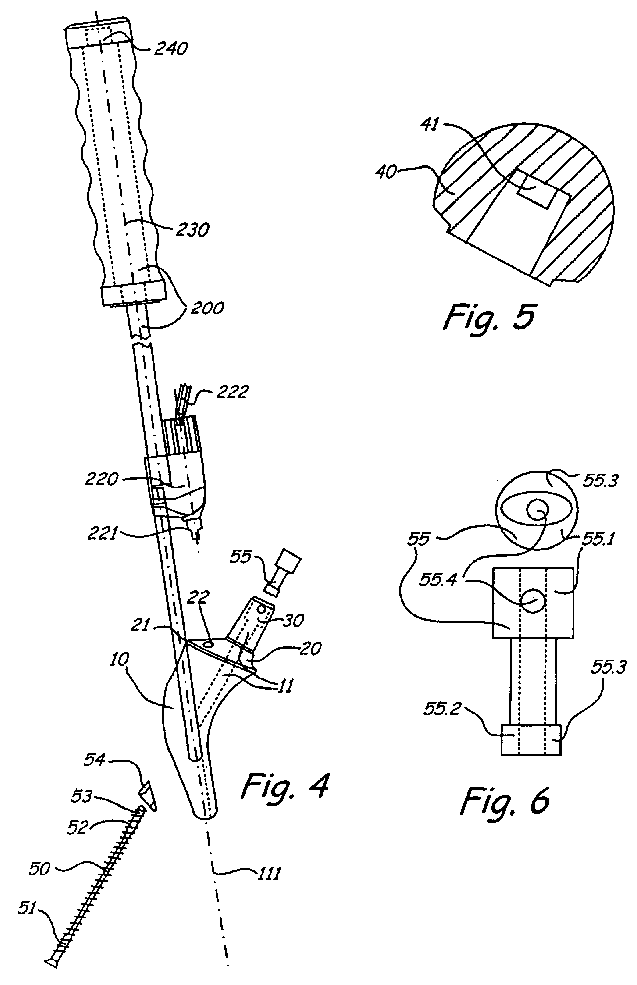
The intermedullary canal is probed using the guide instrument 200, and if this can be done without meeting resistance, the axis 111 of the femoral canal 100A has been correctly established. Then the spongiosa of the metaphysis together with the spongiosa of the femur neck 120 are ground until the trial prosthesis can be inserted into the femoral canal....


PUM


Abstract

A hip prosthesis constructed to transfer forces to the femur without relative movements that cause failures. The prosthesis stem has an open sided central bore. The proximal end of the prosthesis is configured to seat against interior surfaces of the femoral canal and support a femur head on a prosthesis shoulder that seats on the stem proximal end while maintaining the neck of the femur intact.

Description

Anatomically, the neck of the femur is the strongest part of the human skeleton. For this reason, it made sense to preserve it in hip joint replacements. This led to various attempts to cap the head of the femur neck. However, this application of force beneath the cap soon resulted in rocking motions of the implant shell, and bone resorption as a result of the relative movement. This ultimately led to fractures of the femoral neck. Based on histopathological research on this approach to anchoring, it was concluded that a sudden change in rigidity between the implant and the bone can only be transferred to the bone in the centrifugal direction by an intramedullary implant.Accordingly, the object of this invention is to achieve a uniform transfer of force from a rigid implant to the bone.PRIOR ARTMany attempts have been made to anchor prosthesis stems in the femoral neck. For example, in the case of a thrust-plate prosthesis, Huggler and Jacob attempted--with partial success--to ancho...

Claims


Application Information

Patent Timeline
Patent Type & Authority Patents(United States)
IPC IPC(8): A61F2/36A61F2/46A61F2/30A61F2/00
CPCA61F2/36A61F2/4607A61F2/4684A61F2/3601A61F2002/30131A61F2002/30133A61F2002/30233A61F2002/30329A61F2002/30332A61F2002/3038A61F2002/30616A61F2002/30772A61F2002/30794A61F2002/30797A61F2002/3611A61F2002/3625A61F2002/3647A61F2002/365A61F2002/3684A61F2002/3694A61F2002/3696A61F2220/0025A61F2220/0033A61F2230/0013A61F2230/0015A61F2230/0069A61F2310/00017A61F2310/00023A61F2310/00029A61F2310/00131A61F2310/00179A61F2002/30331A61F2002/3079A61F2002/368A61F2002/30594
Inventor DRAENERT, KLAUSWALKER, NORBERT
Owner THURGAUER KANTONALBANK A CHARTERED IN & EXISTING UNDER THE LAWS OF SWITZERLAND THAT MAINTAINS ITS PRINCIPAL OFFICES AT
Why Eureka
Try Eureka