Annulus-reinforcing band

a technology of annulus and reinforcing bands, which is applied in the field of annulus reinforcing bands, can solve the problems of mechanical back pain, many less than ideal bak and many similarly structured rigid metallic implants, paralysis or even death by hemorrhage, etc., and achieves the effects of reducing the distance between the vertebrae, and reducing the risk of fractur

Inactive Publication Date: 2004-03-30
SPINEOLOGY
View PDF39 Cites 406 Cited by
  • Summary
  • Abstract
  • Description
  • Claims
  • Application Information

AI Technical Summary

Benefits of technology

Any device that would more easily, and / or more effectively, and / or more safely treat degenerative disc disease would be useful in the management of hundreds of thousands of suffering individuals.
In at least one embodiment, the invention consists of any continuous band or ring that would be placed around and near the outer margin of the intervertebral disc. A suture or preferably a flattened, braided or woven strand or cord, for instance, that was placed circumferentially about a disc and tied to make a tension-resisting ring, would qualify. Modern endoscopic surgical tools, combined with sophisticated surgical navigation systems make this option more practical and safer than would have been possible a few years ago.

Problems solved by technology

Many studies have concluded that mechanical back pain is the most common and costly musculoskeletal condition affecting middle-aged humans in modem societies.
Unfortunately, the BAK and many similarly structured rigid metallic implants suffer from several less than ideal features such as: the need to create fairly large surgical exposures, the need for fairly large entrance holes through the annulus of the disc, and the presence of fairly large volumes of metal that reduce bone graft surface contact at the end plate.
Heat can be injurious to local spinal nerves and vessels, possibly leading to paralysis or even death by hemorrhage.
The placement of pedicle screws requires a significant surgical exposure with attendant bleeding and injury to local muscular, ligamentous, vascular and nervous tissues.

Method used


Image

  • Annulus-reinforcing band
  • Annulus-reinforcing band
  • Annulus-reinforcing band

Examples


Embodiment Construction

is hereafter described with specific reference being made to the following drawings.

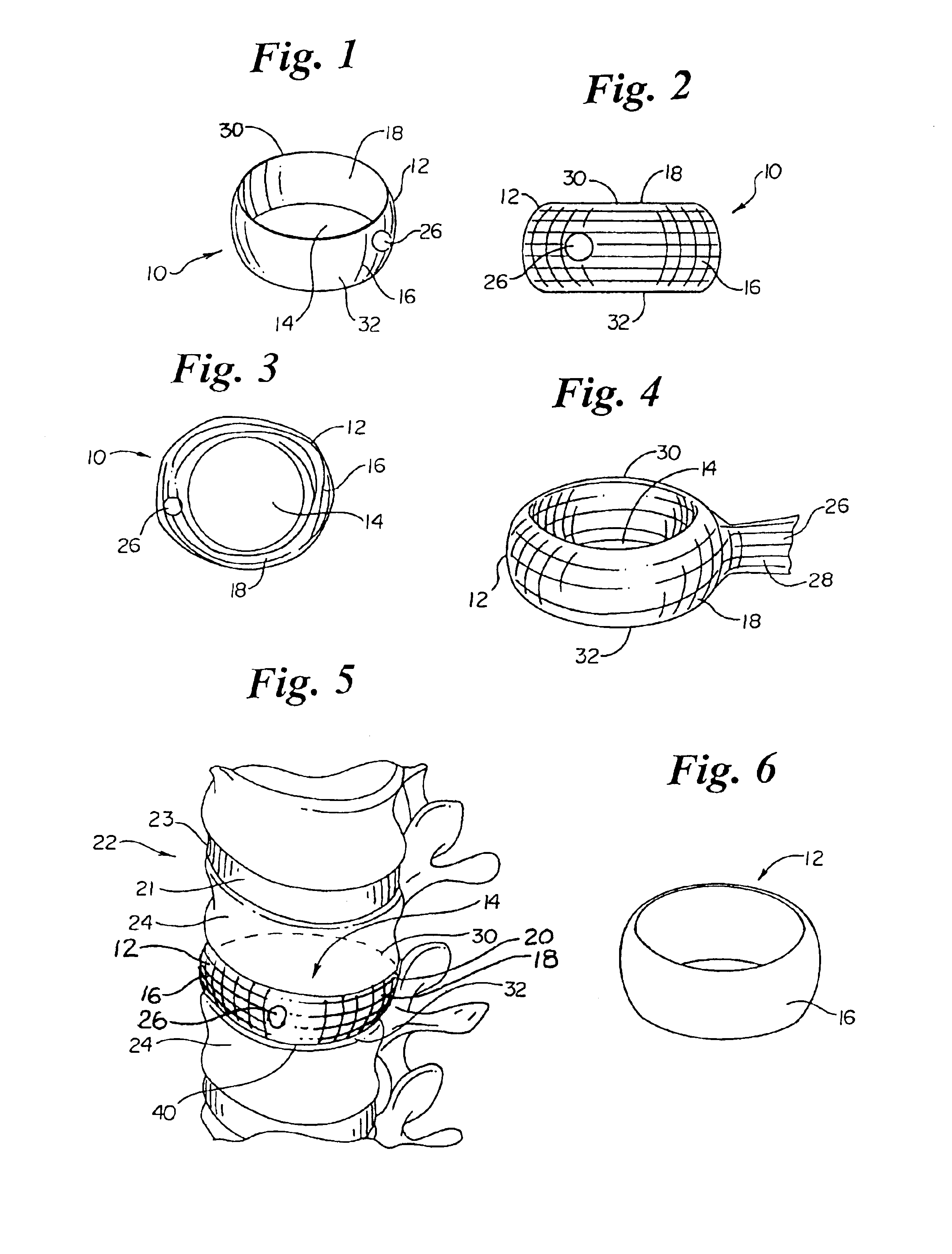
FIG. 1 is a perspective view of a first embodiment of the invention;.

FIG. 2 is a side view of the embodiment of FIG. 1.

FIG. 3 is a top view of the embodiment of FIG. 1.

FIG. 4 is a perspective view of an embodiment of the invention having an elongate fill opening.

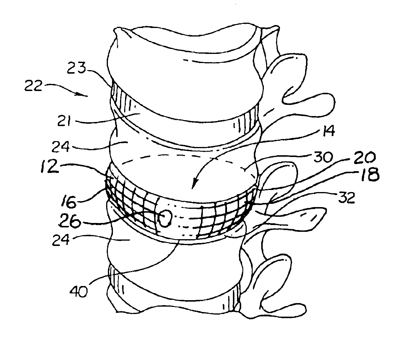
FIG. 5 is a perspective view of an embodiment of the invention as it may appear when used to replace a spinal disc.

FIG. 6 is a perspective view of an embodiment of the invention wherein the band is a molded material.

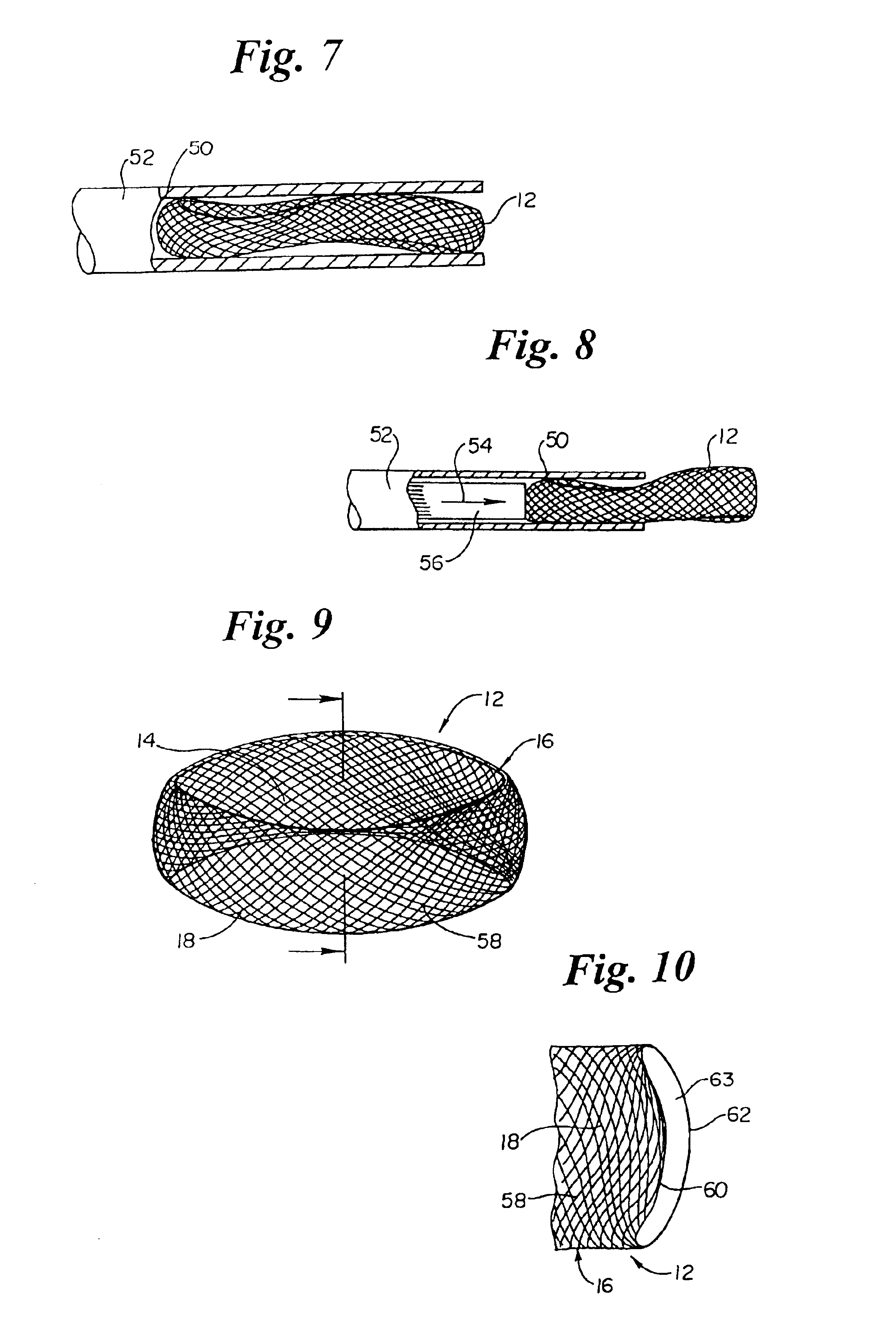
FIG. 7 is a side view of an embodiment of the invention shown in the reduced state within a storage / delivery tool.

FIG. 8 is a side view of the embodiment shown in FIG. 7 wherein the inventive band is being removed from the storage / delivery tool.

FIG. 9 is a perspective view of an embodiment of the invention wherein the inventive band has a woven, double walled configuration.

FIG. 10 is a perspective cut away view of the embodiment s...


PUM

PropertyMeasurementUnit
diameteraaaaaaaaaa
flexibleaaaaaaaaaa
polymericaaaaaaaaaa

Abstract

A pliable band or hoop that is flexible to normal handling, but cannot stretch circumferentially once it has reached the limits of its circumferential length. The band may have a structural portal to be used for filling, or it may simply be constructed of a fabric-like material that allows a fill tube to perforate its walls to allow for filling. In the latter case, the perforated wall tends to self-seal once the fill tube is withdrawn. The band may be flat or tubular in cross-section. However, unlike a balloon, the band does not require either a bottom or a top, as we found that a top and bottom are unnecessary when using a band or hoop to enclose material injected into a reamed out intervertebral space.

Description

Not Applicable.1. Field of the InventionThis invention relates to devices that provide a means to support and / or reinforce and / or stabilize a diseased mammalian spinal intervertebral disc.2. Description of the Related ArtIt is recognized that the spinal disc consists of three parts: first, the nucleus, a central portion that is a compression-resisting cushion; second, the annulus, a peripheral rim portion that is a tension-resisting hoop; and third, the end plate, the superior and inferior borders of the disc, consisting of the up and down borders of the vertebral body bones.Many studies have concluded that mechanical back pain is the most common and costly musculoskeletal condition affecting middle-aged humans in modem societies. Mechanical back pain may be caused by several factors, but overwhelming evidence suggests that degeneration of the spinal intervertebral disc, such as may be caused by Degenerative Disc Disease (DDD) is the most common condition causing back pain symptoms....

Claims


Application Information

Patent Timeline
Patent Type & Authority Patents(United States)
IPC IPC(8): A61B17/70A61F2/44A61F2/46A61F2/30A61F2/28A61F2/00A61N1/20A61B17/88
CPCA61F2/441A61F2/442A61F2/4601A61F2/4611A61B17/7095A61B17/7098A61F2002/2817A61F2002/2821A61F2002/2835A61F2002/30092A61F2002/302A61F2002/30563A61F2002/30677A61F2002/30678A61F2002/30841A61F2002/4435A61F2002/4475A61F2002/4495A61F2002/4627A61F2002/4631A61F2002/4635A61F2210/0014A61F2230/0065A61F2310/00017A61F2310/00023A61F2310/00071A61F2310/00179A61F2002/444A61F2002/30593A61F2/44
Inventor KUSLICH, STEPHEN D.
Owner SPINEOLOGY
Why Eureka
Try Eureka