Braking device for watercraft

a technology for watercraft and braking device, which is applied in the direction of marine propulsion, special-purpose vessels, vessel construction, etc., can solve the problem of prone to damage of baffles

Inactive Publication Date: 2004-04-20
YAMAHA MOTOR CO LTD
View PDF6 Cites 27 Cited by
  • Summary
  • Abstract
  • Description
  • Claims
  • Application Information

AI Technical Summary

Problems solved by technology

In the lowered position, however, the baffle is susceptible to damage as the baffle can strike underwater or floating objects such as, for example, driftwood.

Method used


Image

  • Braking device for watercraft
  • Braking device for watercraft
  • Braking device for watercraft

Examples


Embodiment Construction

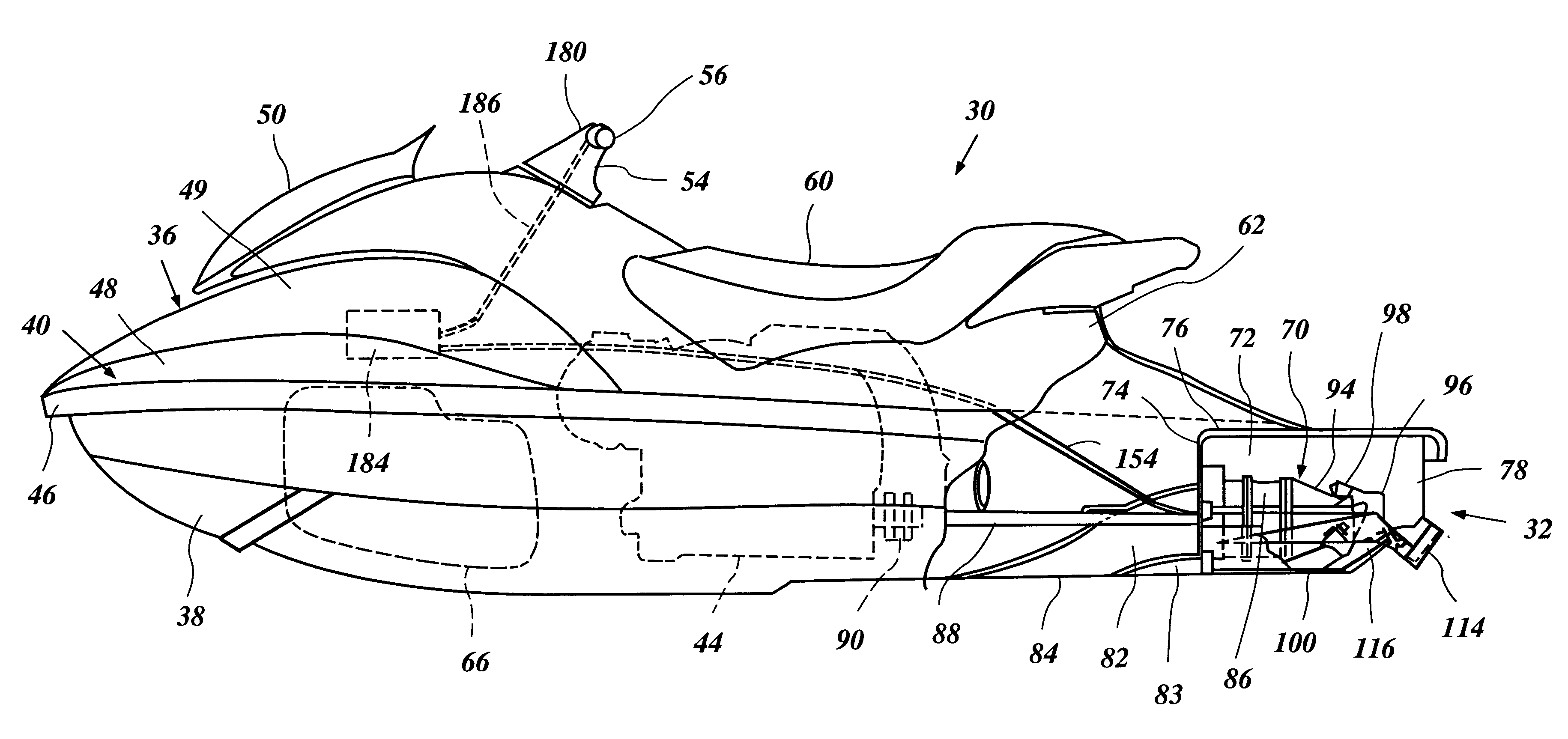
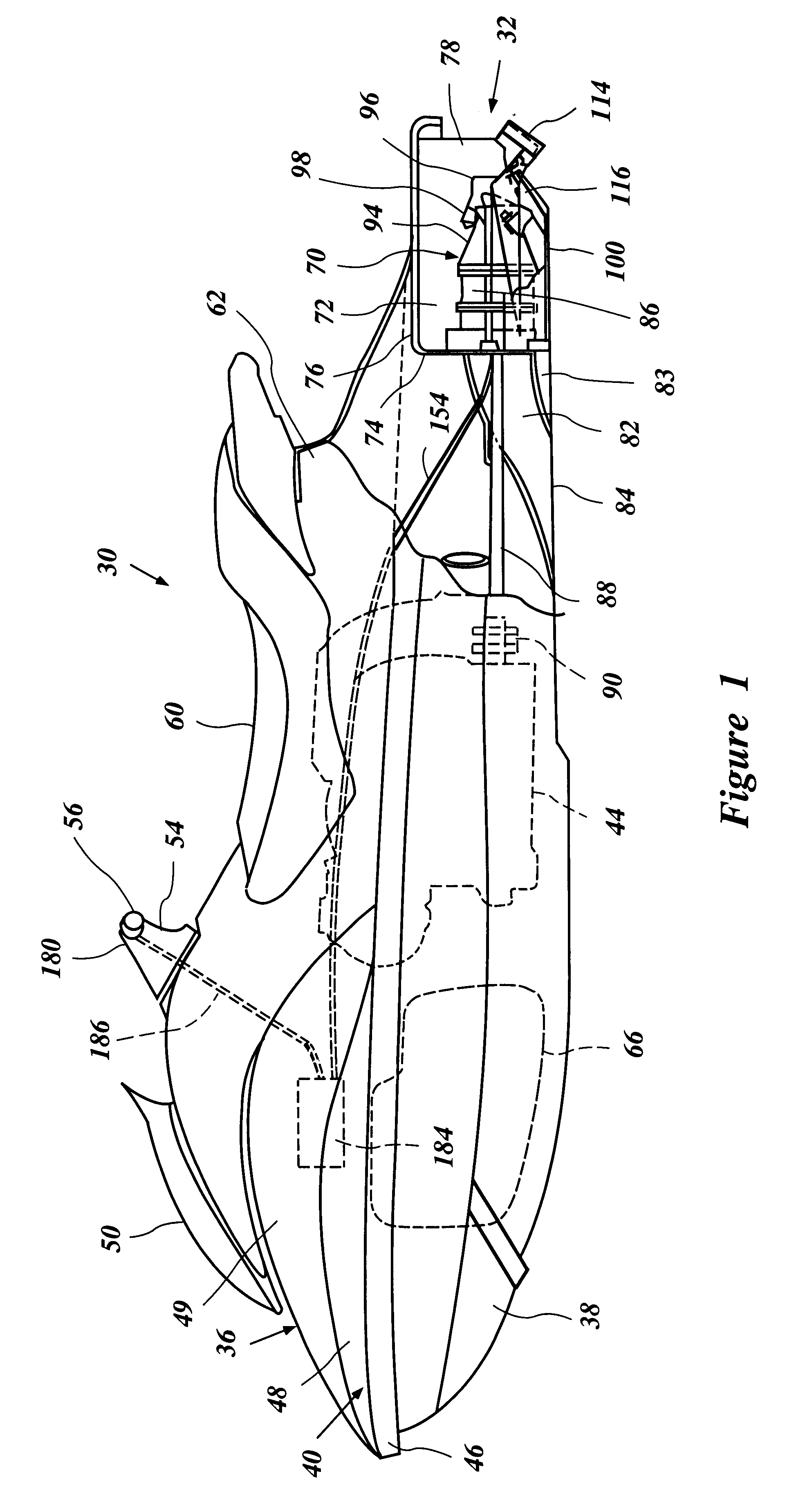
FIG. 1 illustrates an overall construction of a personal watercraft 30 configured in accordance with a preferred embodiment of the present invention. The watercraft 30 includes a braking device or mechanism 32 at a rear end thereof. The braking device has particular utility in the context of a personal watercraft, and thus, is described in this context. The braking device, however, can be used with other types of watercrafts (i.e., jet boats, motor boats, etc.) as will become apparent to those of ordinary skill in the art.

The personal watercraft 30 includes a hull 36 formed with a lower hull section 38 and an upper hull section or deck 40. Both the hull sections 38, 40 are made of, for example, a molded fiberglass reinforced resin or a sheet molding compound. The lower hull section 38 and the upper hull section 40 are coupled together to form an internal cavity that defines at least an engine compartment 42. The engine compartment 42 houses an internal combustion engine 44 therein. ...


PUM


Abstract

A watercraft includes an improved braking device to assist slowing the watercraft when operated. The braking device includes a baffle plate and a guide plate. The baffle plate is movable between a non-braking position and a fully braking position. The guide plate cooperates with the baffle plate and is movable between a normal position and a fully deployed position. With the guide plate in the fully deployed position and the baffle plate in the fully braking position, the guide plate directs water against the baffle plate in order to slow the watercraft.

Description

This application is based on and claims priority to Japanese Patent Application No. 2001-136928, filed on May 8, 2001, the entire content of which is hereby incorporated by reference.1. Field of the InventionThe present invention relates generally to a braking device for a watercraft.2. Description of Related ArtRelatively small watercrafts such as, for example, personal watercrafts have become very popular in recent years. This type of watercraft is quite sporting in nature and carries one or more riders. A hull of the watercraft typically defines a rider's area above an engine compartment. An internal combustion engine powers a jet propulsion unit that propels the watercraft by discharging water rearwardly. The engine lies within the engine compartment in front of a tunnel or gullet that is formed on an underside of the hull. The jet propulsion unit is placed within the tunnel and includes an impeller that is driven by the engine. The jet propulsion unit includes a discharge nozzl...

Claims


Application Information

Patent Timeline
Patent Type & Authority Patents(United States)
IPC IPC(8): B63H25/44B63H25/00B63H11/107B63H11/00B63H25/46B63H11/08B63H11/11
CPCB63H25/44B63H11/107
Inventor YANAGIHARA, TSUIDE
Owner YAMAHA MOTOR CO LTD
Why Eureka
Try Eureka