Ejector cycle system

a cycle system and ejector technology, applied in the direction of transportation and packaging, refrigeration components, light and heating equipment, etc., can solve the problems of deteriorating coefficient of performance (cop) excessive increase of the flow rate of the radiator, and deterioration of the cycle balance of the ejector cycle system

Inactive Publication Date: 2004-05-04
DENSO CORP
View PDF12 Cites 37 Cited by
  • Summary
  • Abstract
  • Description
  • Claims
  • Application Information

AI Technical Summary

Problems solved by technology

As a result, the flow rate in the radiator is excessively increased.
Therefore, a cycle balance in the ejector cycle system is deteriorated, coefficient of performance (COP) of the ejector cycle system is deteriorated.
On the other hand, when the nozzle diameter is set smaller for obtaining a suitable decompression degree (throttle degree) in the low heat load, the load of the compressor is excessively increased when the refrigerant flow amount increases in the high heat load.

Method used


Image

  • Ejector cycle system
  • Ejector cycle system
  • Ejector cycle system

Examples


Embodiment Construction

A preferred embodiment of the present invention will be described hereinafter with reference to the accompanying drawings.

In this embodiment, the present invention is typically applied to an ejector cycle system for a vehicle air conditioner, in which carbon dioxide (CO2) is used as refrigerant.

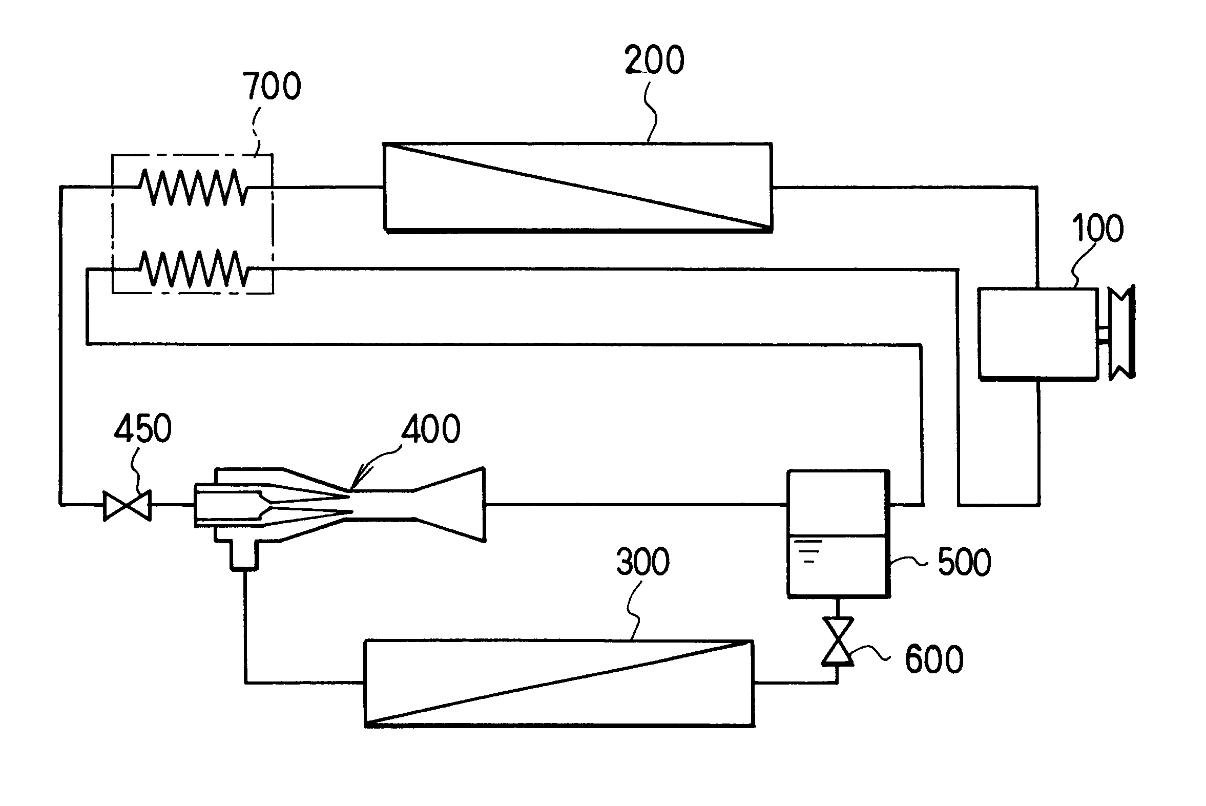
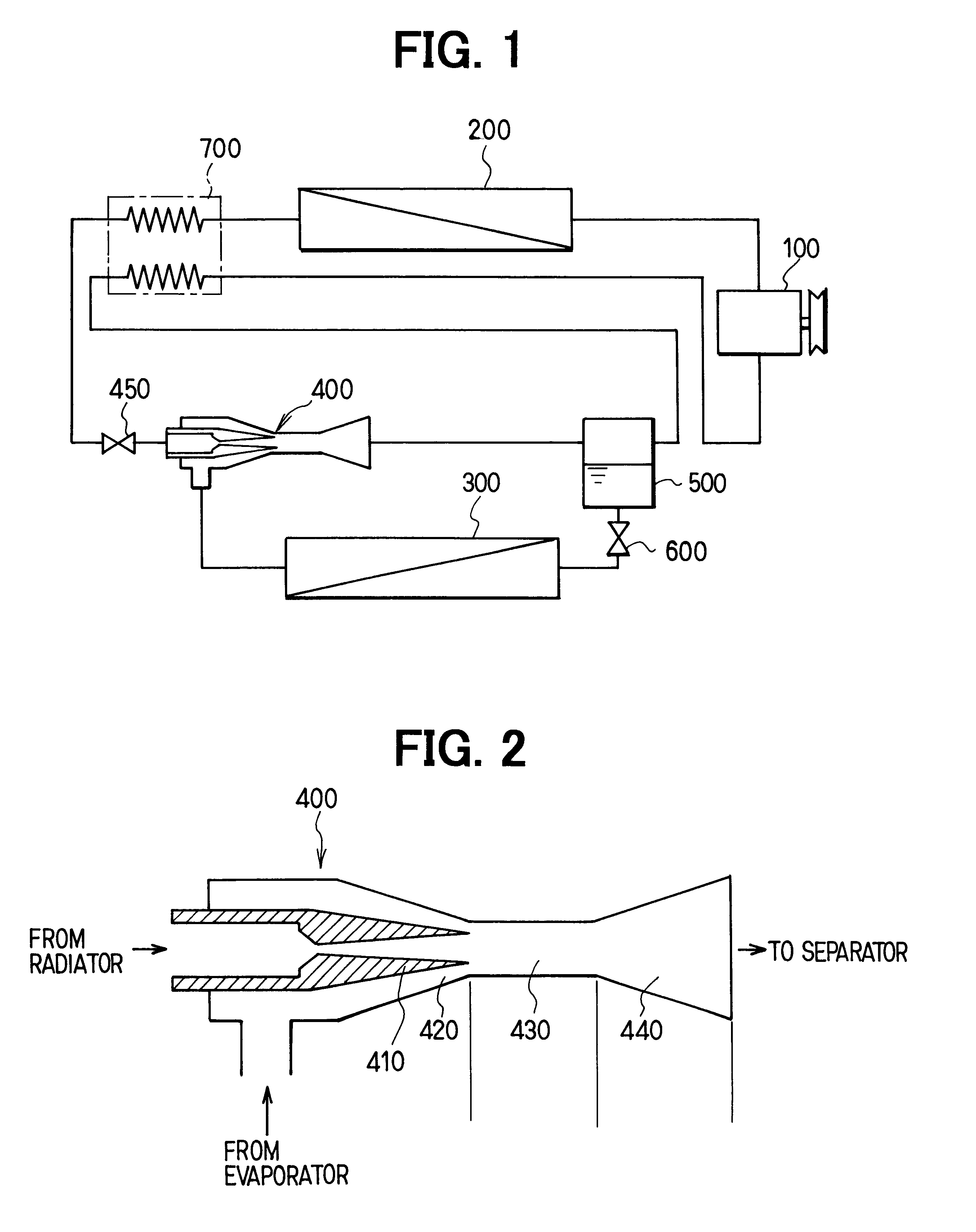
In the embodiment, a compressor 100 is driven by a driving source such as a vehicle engine (not shown) to suck and compress refrigerant (e.g., carbon dioxide in the first embodiment). In a radiator 200 (i.e., high-pressure side heat exchanger), refrigerant discharged from the compressor 100 is heat-exchanged with air (outside air) outside a passenger compartment. The compressor 100 is a variable displacement compressor where a discharge capacity (discharge flow amount) is controlled so that temperature of refrigerant to be sucked to the compressor 100 becomes to a predetermined temperature.

In an evaporator 300 (i.e., low-pressure side heat exchanger), liquid refrigerant in the ejector cycle s...


PUM


Abstract

In an ejector cycle system, a variable throttle is disposed at an upstream side of an ejector. When high-pressure side refrigerant pressure in the ejector cycle system is approximately equal to or higher than critical pressure of the refrigerant, the variable throttle is fully opened. When the high-pressure side refrigerant pressure is approximately lower than the critical pressure of the refrigerant, a throttle open degree of the variable throttle is reduced from the fully open degree so that high-pressure side refrigerant is decompressed in two steps of the variable throttle and the ejector. Accordingly, in both cases of a high heat load and a low heat load of the ejector cycle system, COP of the ejector cycle system can be improved.

Description

This application is related to Japanese Patent Applications No. 2001-308901 filed on Oct. 4, 2001, and No. 2002-241850 filed on Aug. 22, 2002, the contents of which are hereby incorporated by reference.1. Field of the InventionThe present invention relates to an ejector cycle system with two-step refrigerant decompression.2. Description of Related ArtIn an ejector cycle system described in JP-A-6-11197, an ejector sucks gas refrigerant evaporated in an evaporator at a low pressure side, and increases a pressure of refrigerant to be sucked into a compressor by converting an expansion energy to a pressure energy. In the ejector cycle system, a nozzle is constructed by a fixed throttle. Therefore, when heat load of the ejector cycle system changes, a flow amount of refrigerant flowing into the ejector is changed, and a decompression degree (throttle degree) in the nozzle is changed. Specifically, in a cooling device, when the outside air temperature is low and the heat load becomes sma...

Claims


Application Information

Patent Timeline
Patent Type & Authority Patents(United States)
IPC IPC(8): B60H1/32F25B41/00F25B9/00F25B40/00F25B1/00F25B9/08
CPCB60H1/3204F25B41/00B60H2001/3297B60H2001/3298F25B9/008F25B40/00F25B2309/061F25B2341/0011F25B2341/0012F25B2341/066F25B41/385F25B41/39F25B9/08
Inventor TAKEUCHI, HIROTSUGU
Owner DENSO CORP
Why Eureka
Try Eureka